11.2 VARIABLE FREQUENCY GENERATOR
CALIBRATION
The large number of crystal controlled fre-
quency markers available in the Model 415
make
it an ideal instrument for calibration
of tunable generators. Direct frequency
calibration can be performed or harmonic
relationships between the generator and
the Model 415 can be used to calibrate an
unusually extensive range of frequencies.
11.2.1 Connect the Model 415 to an oscilloscope
as indicated in Figure 5.2.
11.2.2 Connect the signal generator to be cali-
brated at the EXT MARKER IN jack of the
Model 415.
11.2.3 Place the FUNCTION switch of the Model
415 to the IF position. Make sure the
CHROMA switch is in the OFF position.
11.2.4 Select the internal marker of the Model 415
against which
it is desired to calibrate the
tunable generator. Center this marker on
the oscilloscope screen, using the MARKER
AMPLITUDE control to set the desired
height. Use one to two volts peak-to-peak
marker amplitude.
11.2.5 Tune the generator to the marker frequency.
Adjust the tunable generator output so that
a marker is visible on the oscilloscope trace.
Adjust the tunable generator until the two
markers coincide. A beat frequency will be
observed on the oscilloscope as the vari-
able frequency marker approaches the
crystal reference marker from one side and
passes to the other side. Set the tunable
generator marker in the center of the
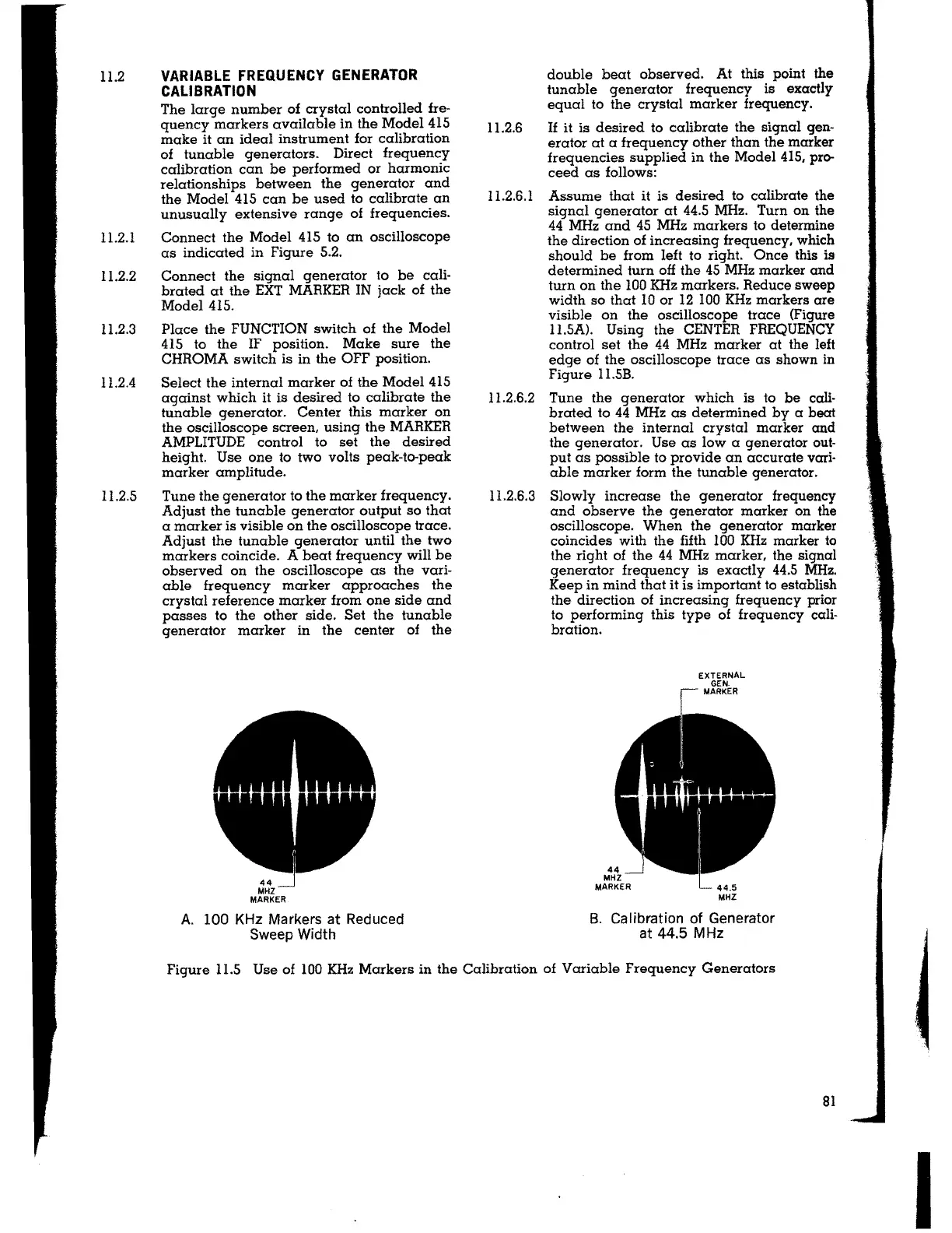
A. 100 KHz Markers at Reduced
Sweep Width
double beat observed. At this point the
tunable generator frequency is exactly
equal to the crystal marker frequency.
11.2.6 If it is desired to calibrate the signal gen-
erator at a frequency other than the marker
frequencies supplied in the Model 415, pro-
ceed as follows:
11.2.6.1 Assume that it is desired to calibrate the
signal generator at 44.5 MHz. Turn on the
44 MHz and 45 MHz markers to determine
the direction of increasing frequency, which
should be from left to right. Once this
is-
determined turn off the 45 MHz marker and
turn on the 100 KHz markers. Reduce sweep
width so that 10 or 12 100 KHz markers are
visible on the oscilloscope trace (Figure
11.5A). Using the CENTER FREQUENCY
control set the 44 MHz marker at the left
edge of the oscilloscope trace as shown in
Figure 11.5B.
I 1.2.6.2 Tune the generator which is to be cali-
brated to 44 MHz as determined by a beat
between the internal crystal marker and
the generator. Use as low a generator out-
put as possible to provide an accurate vari-
able marker form the tunable generator.
11.2.6.3 Slowly increase the generator frequency
and observe the generator marker on the
oscilloscope. When the generator marker
coincides with the fifth 100 KHz marker to
the right of the 44 MHz marker, the signal
generator frequency is exactly 44.5 MHz.
Keep in mind that it is important to establish
the direction of increasing frequency prior
to performing this type of frequency cali-
bration.
B. Calibration of Generator
at 44.5 MHz
Figure I 1.5 Use of 100 KHz Markers in the Calibration of Variable Frequency Generators
81
I