18
located at resonance. The effect of slug loca-
tions is also important in double-tuned coil
assemblies for similar reasons. Figure 2.12A
shows a double-tuned transformer with the
equivalent electrical circuit in Figure 2.12B.
Either tuned circuit of Figure 2.12A can be
resonated with the slugs at position
1 or 2.
The coil spacing is designed to give the de-
sired response when the tuned circuits are
resonated with the slugs in only one position,
usually position
1. If the circuits are tuned
with either slug in position
2, the coupling
will be greater (possibly overcoupled). If the
circuits are tuned with both slugs in position
2, greater overcoupling will occur. The range
of response curves shown in Figure 2.10 can
be obtained from the double-tuned coil as-
sembly of Figure 2.12A by varying the slug
positions.
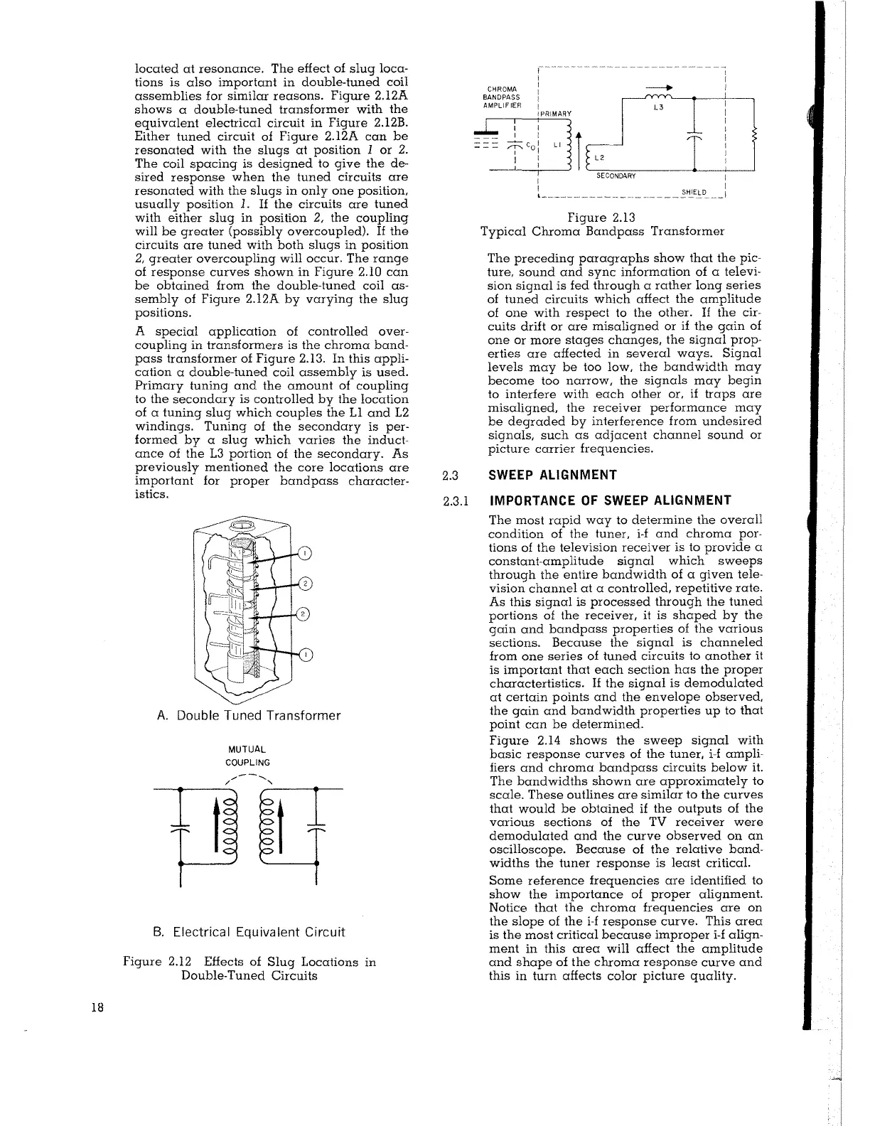
A special application of controlled over-
coupling in transformers is the chroma band-
pass transformer of Figure 2.13. In this appli-
cation a double-tuned coil assembly is used.
Primary tuning and the amount of coupling
to the secondary is controlled by the location
of a tuning slug which couples the Ll and 12
windings. Tuning of the secondary is per-
formed by a slug which varies the induct-
ance of the 13 portion of the secondary. As
previously mentioned the core locations are
important for proper bandpass character-
istics.
A. Double Tuned Transformer
MUTUAL
COUPLING
.,,,,--.......
/
'
t
t
B. Electrical Equivalent Circuit
Figure 2.12 Effects of Slug Locations in
Double-Tuned Circuits
Figure 2.13
Typical Chroma Bandpass Transformer
The preceding paragraphs show that the pic-
ture, sound and sync information of a televi-
sion signal is fed through a rather long series
of tuned circuits which affect the amplitude
of one with respect to the other.
If the cir-
cuits drift or are misaligned or if the gain of
one or more stages changes, the signal prop-
erties are affected in several ways. Signal
levels may be too low, the bandwidth may
become too narrow, the signals may begin
to interfere with each other or, if traps are
misaligned, the receiver performance may
be degraded by interference from undesired
signals, such as adjacent channel sound or
picture carrier frequencies.
2.3
SWEEP ALIGNMENT
2.3.l IMPORTANCE OF SWEEP ALIGNMENT
The most rapid way to determine the overall
condition of the tuner, i-f and chroma por-
tions of the television receiver is to provide a
constant-amplitude signal which sweeps
through the entire bandwidth of a given tele-
vision channel at a controlled, repetitive rate.
As this signal is processed through the tuned
portions of the receiver, it is shaped by the
gain and bandpass properties of the various
sections. Because the signal is channeled
from one series of tuned circuits to another
it
is important that each section has the proper
charactertistics. If the signal is demodulated
at certain points and the envelope observed,
the gain and bandwidth properties up to that
point can be determined.
Figure 2.14 shows the sweep signal with
basic response curves of the tuner, i-f ampli-
fiers and chroma bandpass circuits below it.
The bandwidths shown are approximately to
scale. These outlines are similar to the curves
that would be obtained if the outputs of the
various sections of the TV receiver were
demodulated and the curve observed on an
oscilloscope. Because of the relative band-
widths the tuner response is least critical.
Some reference frequencies are identified to
show the importance of proper alignment.
Notice that the chroma frequencies are on
the slope of the i-f response curve. This area
is the most critical because improper i-f align-
ment in this area will affect the amplitude
and shape of the chroma response curve and
this in turn affects color picture quality.