2.2 THE TELEVISION RECEIVER
The basic functions of the television receiver
are to select a specific television channel fre-
quency spectrum, process the signals, shape
the frequency spectrum as required by tuned
circuits (either bandpass or trap), demodulate
the frequency information and distribute the
demodulated signals to all the sound and
picture generating circuits. These circuits in-
clude vertical and horizontal sync, sound,
age, video, chroma circuits-all the circuits
following the detectors.
2.2.1 TYPICAL TELEVISION RECEIVER BLOCK
DIAGRAMS
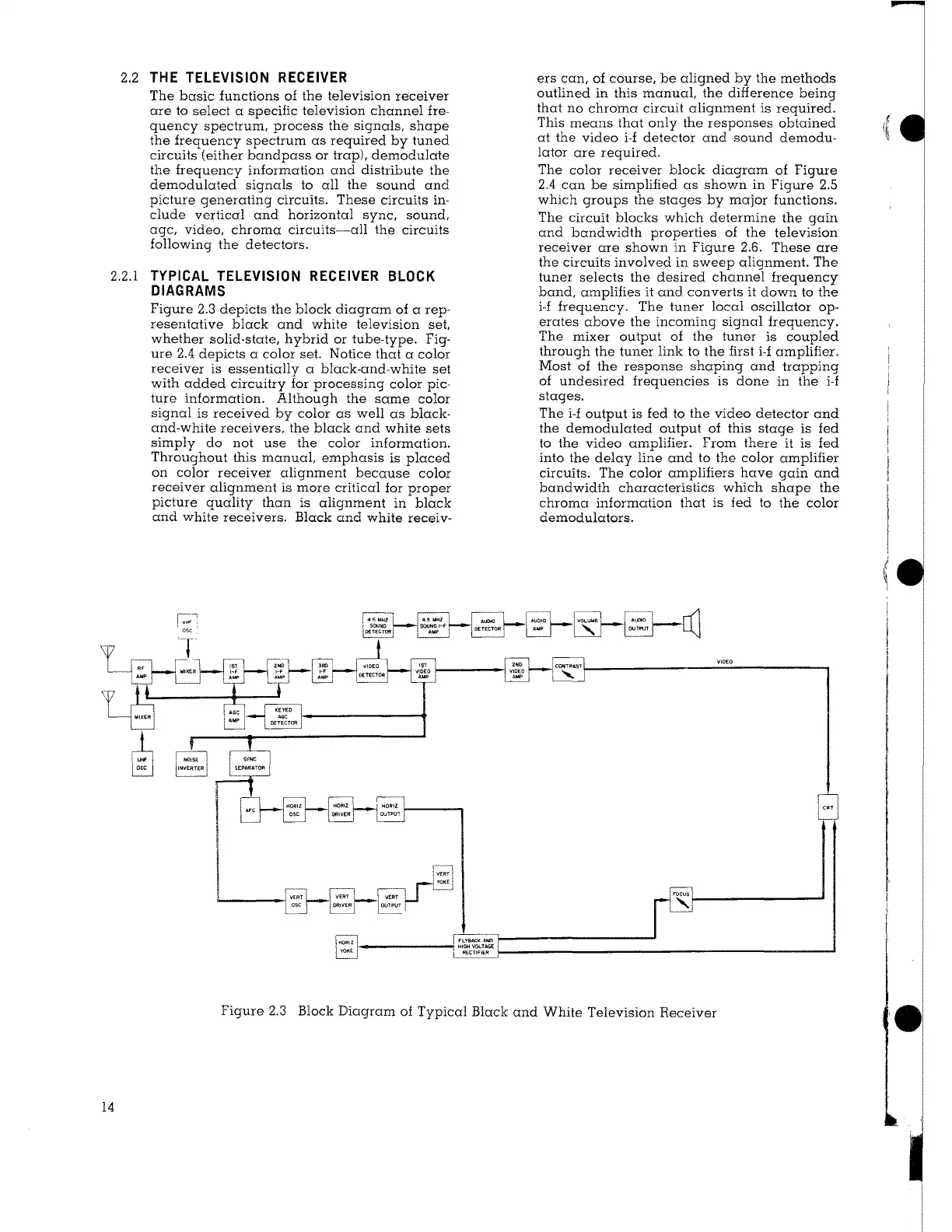
Figure 2.3 depicts the block diagram of a rep-
resentative black and white television set,
whether solid-state, hybrid or tube-type. Fig-
ure 2.4 depicts a color set. Notice that a color
receiver is essentially a black-and-white set
with added circuitry for processing color pic-
ture information. Although the same color
signal is received by color as well as black-
and-white receivers, the black and white sets
simply do not use the color information.
Throughout this manual, emphasis is placed
on color receiver alignment because color
receiver alignment is more critical for proper
picture quality than is alignment in black
and white receivers. Black and white receiv-
r---;1
El
r:;,;l .J
I OUTPC.IT I
ers can, of course, be aligned by the methods
outlined in this manual, the difference being
that no chroma circuit alignment is required.
This means that only the responses obtained
at the video
i-f detector and sound demodu-
lator are required.
The color receiver block diagram of Figure
2.4 can be simplified as shown in Figure 2.5
which groups the stages by major functions.
The circuit blocks which determine the gain
and bandwidth properties of the television
receiver are shown in Figure 2.6. These are
the circuits involved in sweep alignment. The
tuner selects the desired channel frequency
band, amplifies it and converts it down to the
i-f frequency. The tuner local oscillator op-
erates above the incoming signal frequency.
The mixer output of the tuner is coupled
through the tuner link to the first
i-f amplifier.
Most of the response shaping and trapping
of undesired frequencies is done in the
i-f
stages.
The
i-f output is fed to the video detector and
the demodulated output of this stage is fed
to the video amplifier. From there it is fed
into the delay line and to the color amplifier
circuits. The color amplifiers have gain and
bandwidth characteristics which shape the
chroma information that is fed lo the color
demodulators.
Figure 2.3 Block Diagram of Typical Black and White Television Receiver
14
(
i