7.0 ALIGNMENT TOUCH-UP PROCEDURES
7.1 PRELIMINARY
When the evaluation of curves obtained in
section 6.1 indicate that the curves are rec-
ognizable but marginal on response limits
and possible trap alignment, the following
must first be done.
7.1.1 Determine from the manufacturer's or
SAMS
procedure whether alignment of the i-f section
is performed by injecting the sweep signal at
the antenna (r-f sweep) or at the mixer (i.f
sweep). The advantage of alignment by in·
jecting at the mixer test point is that the fine
tuning control of the tuner is no longer a
consideration. Tuner bias is then set at a
cut-off value to prevent interference from local
television channels.
7.1.2 Determine the
injection point for introducing
spot frequency markers for prealignment of
the i-f traps and other tuned circuits. This is
usually a mixer test point and is also the
sweep frequency injection point when align-
ment of the i-f stages is performed by injecting
at the mixer.
7.1.3 When the mixer test point is specified for spot
frequency injection for prealignment purposes
only, do not use if for i-f sweep injection. The
test procedure will indicate all injection points
for various alignment tasks.
7.1.4 In reviewing the location and adjustment of
various tuned circuits, note that the location
of the tuning slug with respect to the chassis
or circuit board is specified. Always observe
the instructions in this regard (the importance
of tuning slug locations in tuned circuits is
reviewed in Paragraph 2.2.2). Another pre-
caution regarding tuned circuits, particularly
in older sets, is to beware of broken coil forms
or excessively loose tuning slugs. This is in-
dicated by sudden changes in observed re-
sponse curves when the tuning tool is inserted
or withdrawn from the tuning slug. This
defect must be corrected before completing
alignment because any vibration or shock
can produce a change in the alignment curves.
7.2 TRAP ADJUSTMENTS
If
trap alignment is indicated or is suspected,
proceed as follows. (Use test set-up procedure
of Par. 5.2 and set-up of Figure 5.2):
7.2.1 Locate spot frequency (marker) injection point.
This is usually a test point in the mixer area
of the tuner.
7.2.2 Connect direct probe of Model 415 to the video
detector test point.
7.2.3 Place PROBES switch in DIRECT position.
7.2.4 Apply i-f and r-f age bias voltages as speci-
fied for sweep alignment. This will enable you
to switch between the MOD MKR and IF posi-
tions of the FUNCTION switch as required to
see the effect on the i-f response of adjusting
the traps.
7.2.5 Place FUNCTION switch of 415 in MOD MKR
position.
7.2.6 Connect 415 r-f cable to the signal injection
point of the mixer. Use the 75-ohm termination.
NOTE:
In selection of marker frequencies for trap
alignment select only one marker at a time.
Always use minimum signal level required to
give satisfactory tuning indication.
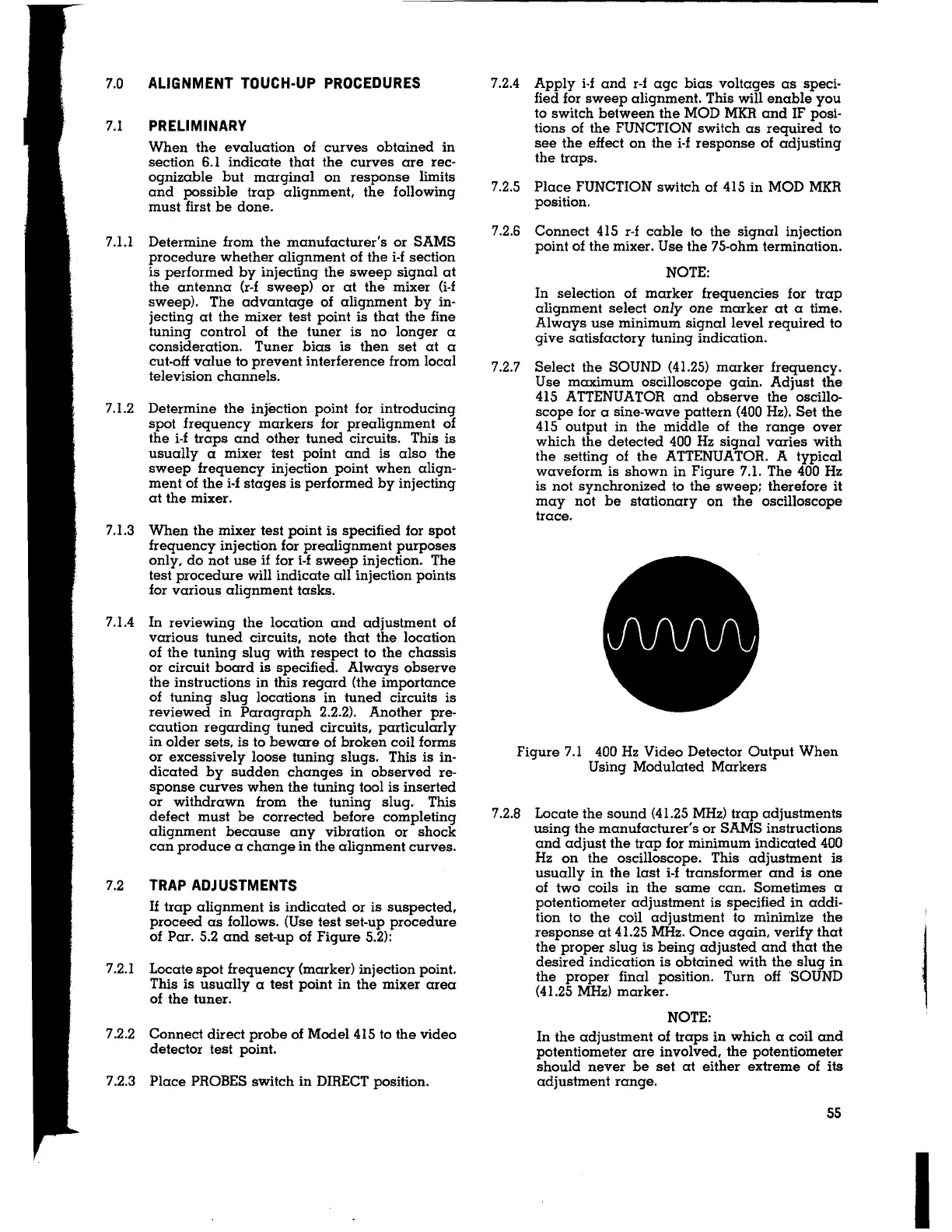
7.2.7 Select the SOUND (41.25) marker frequency.
Use maximum oscilloscope gain. Adjust the
415 ATTENUATOR and observe the oscillo-
scope for a sine-wave pattern (400 Hz). Set the
415 output in the middle of the range over
which the detected 400 Hz signal varies with
the setting of the ATTENUATOR. A typical
waveform is shown in Figure 7.1. The 400 Hz
is not synchronized to the sweep; therefore it
may not be stationary on the oscilloscope
trace.
Figure 7.1 400 Hz Video Detector Output When
Using Modulated Markers
7.2.8 Locate the sound (41.25 MHz) trap adjustments
using the manufacturer's or SAMS instructions
and adjust the trap for minimum indicated 400
Hz on the oscilloscope. This adjustment is
usually in the last i-f transformer and is one
of two coils in the same can. Sometimes a
potentiometer adjustment is specified in addi-
tion to the coil adjustment to minimize the
response at 41.25 MHz. Once again, verify that
the proper slug is being adjusted and that the
desired indication is obtained with the slug in
the proper final position. Turn off 'SOUND
(41.25
MHz) marker.
NOTE:
In the adjustment of traps in which a coil and
potentiometer are involved, the potentiometer
should never be set at either extreme of its
adjustment range.
55
I
 Loading...