MAGNAVOX MODEL T933 TUNER AFC ALIGNMENT USING THE MODEL 415
Before proceeding with the Tuner AFC Alignment, check the overall
response to make sure the curve falls within the limits specified. If necessary
repeat the Video IF and Chroma alignment and then proceed with the follow-
ing instructions:
1. Use test equipment set-up of Figure 5.2 and Section 5.2 of manual.
Connect r-f cable of Model 415 to tuner test point using 75-ohm imped-
ance. Connect Direct cable to Point "B" on the AFC Board. Open the
"AFC Defeat" Switch, i.e., set the "Auto Color" Switch to the "On"
position.
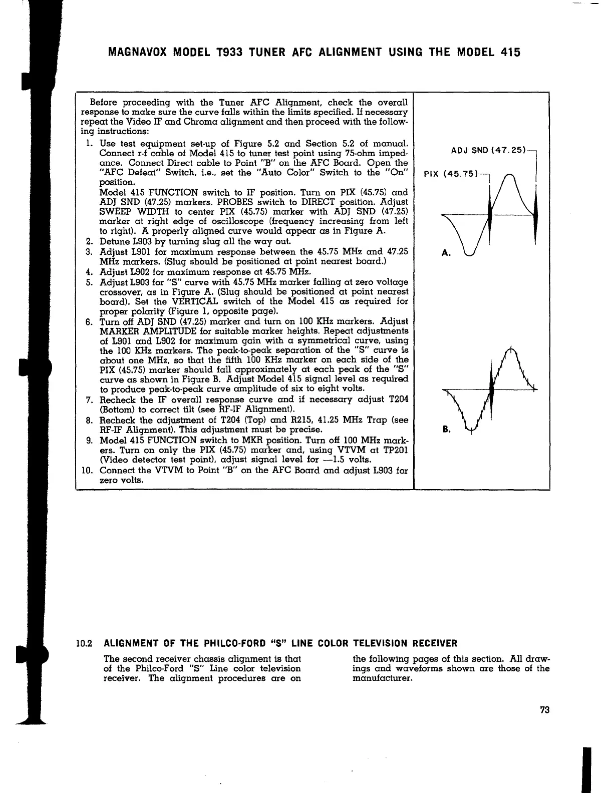
Model 415 FUNCTION switch to IF position. Turn on PIX (45.75) and
ADJ SND (47.25) markers. PROBES switch to DIRECT position. Adjust
SWEEP WIDTH to center PIX (45.75) marker with ADJ SND (47.25)
marker at right edge of oscilloscope (frequency increasing from left
to right). A properly aligned curve would appear as in Figure A.
2. Detune 1903 by turning slug all the way out.
3. Adjust 1901 for maximum response between the 45.75 MHz and 47.25
MHz markers. (Slug should be positioned at point nearest board.)
4. Adjust 1902 for maximum response at 45.75 MHz.
5. Adjust 1903 for
"S" curve with 45.75 MHz marker falling at zero voltage
crossover, as in Figure A. (Slug should be positioned at point nearest
board). Set the VERTICAL switch of the Model 415 as required for
proper polarity (Figure
1, opposite page).
6. Tum off ADJ SND (47.25) marker and turn on 100 KHz markers. Adjust
MARKER AMPLITUDE for suitable marker heights. Repeat adjustments
of 1901 and 1902 for maximum gain with a symmetrical curve, using
the 100 KHz markers. The peak-to-peak separation of the "S" curve is
about one MHz, so that the fifth 100 KHz marker on each side of the
PIX (45.75) marker should fall approximately
at each peak of the "S"
curve as shown in Figure B. Adjust Model 415 signal level as required
to produce peak-to-peak curve amplitude of six to eight volts.
7. Recheck the IF overall response curve and
if necessary adjust T204
(Bottom) to correct tilt (see RF-IF Alignment).
8. Recheck the adjustment of T204 (Top) and R215, 41.25 MHz Trap (see
RF-IF Alignment). This adjustment must be precise.
9. Model 415 FUNCTION switch to MKR position. Turn off 100 MHz mark-
ers. Turn on only the PIX (45.75) marker and, using VTVM at TP201
(Video detector test point), adjust signal level for -1.5 volts.
10. Connect the VTVM to Point "B" on the AFC Board and adjust 1903 for
zero volts.
PIX
ADJ SND (47.
25)
1
(45.75)1
A.
10.2 ALIGNMENT OF THE PHILCO-FORD "S" LINE COLOR TELEVISION RECEIVER
The second receiver chassis alignment is that
of the Philco-Ford
"S" Line color television
receiver. The alignment procedures are on
the following pages of this section. All draw-
ings and waveforms shown are those of the
manufacturer.
73
I