72
ll\llagna'V'o~
MANUAL NO.
SECTION
T933 COLOR TV CHASSIS
ISSUED
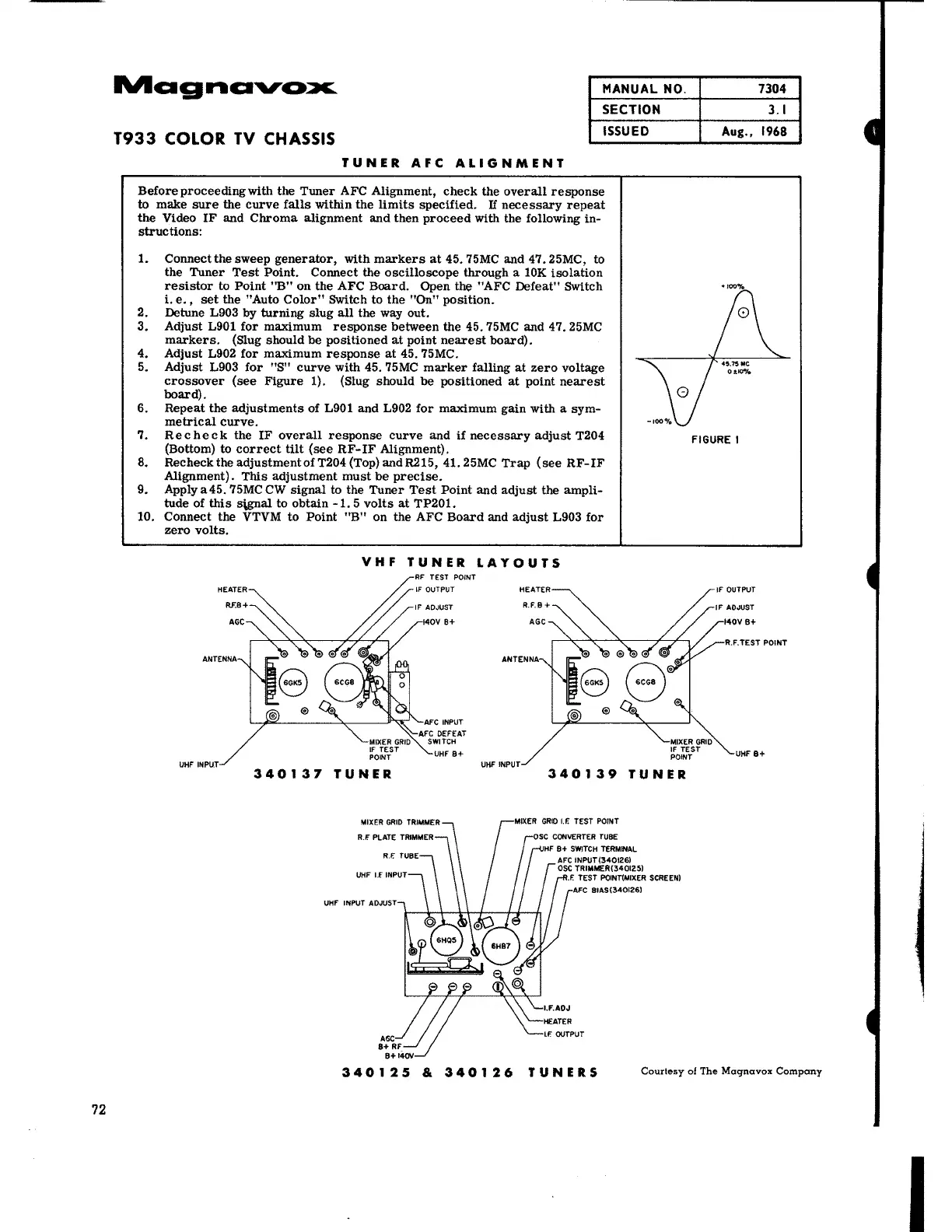
TUNER AFC ALIGNMENT
Beforeproceedingwith the Tuner AFC Alignment, check the overall response
to make sure the curve falls within the limits specified.
If necessary repeat
the Video IF and Chroma alignment and then proceed with the following in-
structions:
1. Connect the sweep generator, with markers at 45. 75MC and 47.25MC, to
the Tuner Test Point. Connect the oscilloscope through a lOK isolation
resistor to Point "B" on the AFC Board. Open the "AFC Defeat" Switch
i.e., set the "Auto Color" Switch to the
"On" position.
2. Detune L903
by turning slug all the way out.
3. Adjust L901 for maximum response between the 45. 75MC and 47. 25MC
markers. (Slug should be positioned at point nearest board).
4. Adjust L902 for maximum response at 45. 75MC.
5. Adjust L903 for "S" curve with 45. 75MC marker falling at zero voltage
crossover (see Figure 1). (Slug should be positioned at point nearest
board).
6. Repeat the adjustments of L901 and L902 for maximum gain with a sym-
metrical curve.
7. Recheck the IF overall response curve and if necessary adjust T204
(Bottom) to correct tilt (see RF-IF Alignment).
8. RechecktheadjustmentofT204(Top)andR215, 41.25MC Trap (see RF-IF
Alignment). This adjustment must be precise.
9. Apply a45. 75MC CW signal to the Tuner Test Point and adjust the ampli-
tude of this S\gllal to obtain
-1. 5 volts at TP201.
10. Connect the
VTVM to Point "B" on the AFC Board and adjust L903 for
zero volts.
VHF TUNER LAYOUTS
340137 TUNER
UHF INPUT ADJUST
HEATER
340139 TUNER
HF B + SWITCH TERMINAL
AFC INPUT (340126)
OSC TRIMMEA{340125l
.F. TEST POINT{MIXER SCREEN)
AFC BIAS (340126)
7304
3.1
Aug .• 1968
FIGURE I
IF OUTPUT
340125 & 340126 TUNERS
Courtesy of The Magnavox Company
I