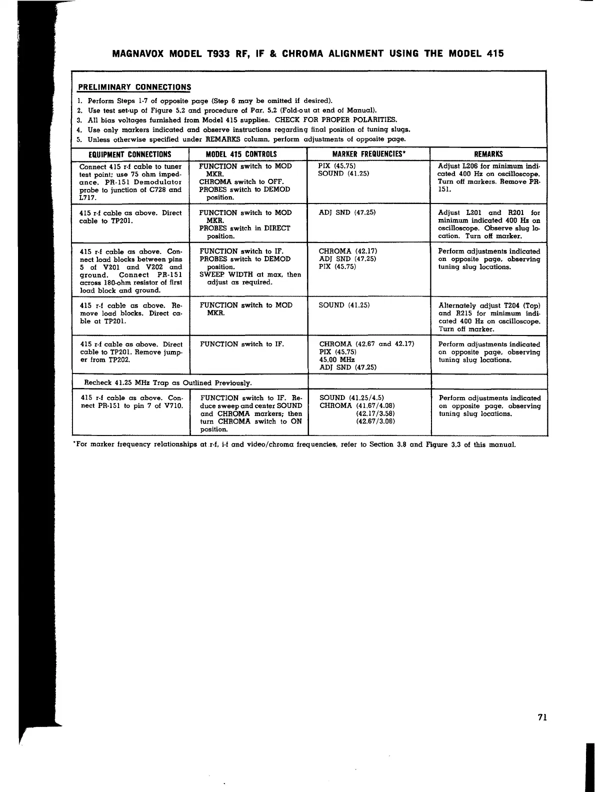
MAGNAVOX MODEL T933 RF, IF & CHROMA ALIGNMENT USING THE MODEL 415
PRELIMINARY CONNECTIONS
1.
Perform Steps 1-7 of opposite page (Step 6 may be omitted if
desired).
2.
Use test set-up of Figure 5.2 and procedure of Par. 5.2 (Fold-out at end of Manual).
3.
All bias voltages furnished from Model 415 supplies. CHECK FOR PROPER POLARITIES.
4.
Use only markers indicated and observe instructions regarding final position of tuning slugs.
5.
Unless otherwise specified under REMARKS column, perform adjustments of opposite page.
EQUIPMENT CONNECTIONS
MODEL 415 CONTROLS
MARKER FREQUENCIES*
REMARKS
Connect 415 r-f cable to tuner
FUNCTION switch to MOD
PIX (45.75)
Adjust 1206 for minimum indi-
test point; use 75 ohm imped-
MXR.
SOUND (41.25)
coted 400 Hz on oscilloscope.
ance.
PR-151 Demodulator
CHROMA switch to OFF.
Turn off markers. Remove
PR-
probe to junction of C728 and
PROBES switch to DEMOD
151.
1717.
position.
415 r-f cable as above. Direct
FUNCTION switch to MOD
ADJ SND (47.25)
Adjust
1201 and R20l for
cable to TP20l.
MKR.
minimum indicated 400 Hz on
PROBES switch in DIRECT
oscilloscope. Observe slug lo-
position.
cation.
Turn off marker.
415
r-f cable as above.
Con- FUNCTION switch to IF.
CHROMA (42.17) Perform adjustments indicated
nect load blocks between pins
PROBES switch to DEMOD
ADJ SND (47.25)
on opposite page, observing
5 of V201
and
V202 and position.
PIX (45.75)
tuning slug locations.
ground.
Connect
PR-151
SWEEP
WIDTH at max, then
across 180-ohm resistor of first
adjust as required.
load block and ground.
415
r-! cable as above.
Re-
FUNCTION switch to MOD
SOUND (41.25)
Alternately adjust T204 (Top)
move load blocks. Direct ca-
MXR. and R215 for minimum indi-
ble at TP20l. cated 400 Hz on oscilloscope.
Turn off marker.
415
r-f cable as above. Direct
FUNCTION switch to IF.
CHROMA (42.67 and 42.17)
Perform adjustments indicated
cable to TP201. Remove
jump-
PIX (45.75)
on opposite page, observing
er from TP202. 45.00 MHz tuning slug locations.
ADJ SND (47.25)
Recheck 41.25 MHz Trap as Outlined Previously.
415 r-f cable as above.
Con- FUNCTION switch to IF. Re-
SOUND (41.25/4.5)
Perform adjustments indicated
nect PR-151 to pin 7 of V710.
duce sweep and center SOUND
CHROMA (41.67/4.08)
on opposite page, observing
and CHROMA markers; then
(42.17/3.58)
tuning slug locations.
turn CHROMA switch to ON
(42.67 /3.08)
position.
·ror marker frequency relationships at r-f. i-1 and video/chroma frequencies, refer to Section 3.8 and Figure 3.3 of this manual.
71
I