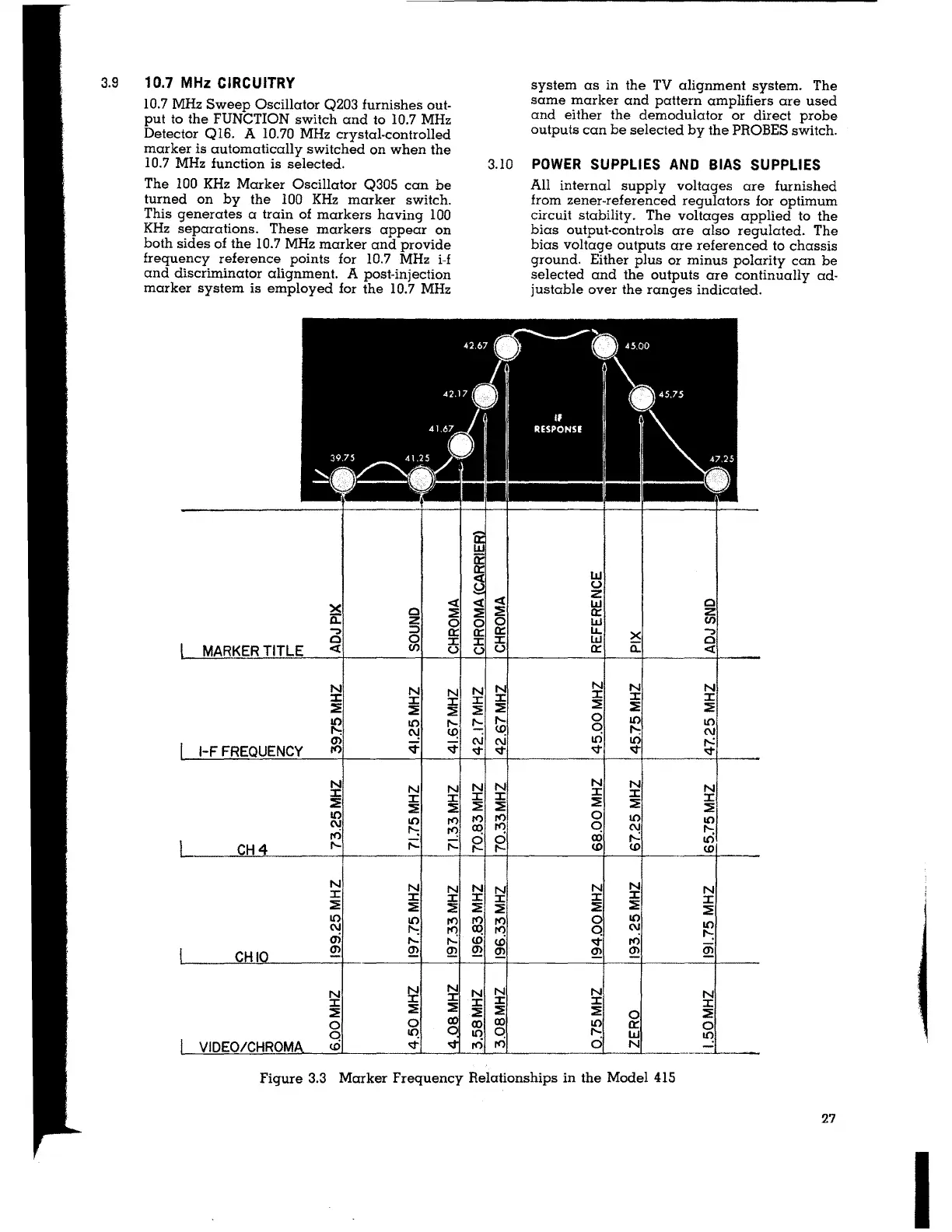
3.9
10.7 MHz CIRCUITRY
10.7 MHz Sweep Oscillator Q203 furnishes out-
put to the FUNCTION switch and to 10.7 MHz
Detector Ql6. A 10.70 MHz crystal-controlled
marker is automatically switched on when the
10.7 MHz function is selected.
The 100 KHz Marker Oscillator Q305 can be
turned on by the 100 KHz marker switch.
This generates a train of markers having 100
KHz separations. These markers appear on
both sides of the 10.7 MHz marker and provide
frequency reference points for 10.7 MHz i-f
and discriminator alignment. A post-injection
marker system is employed for the 10.7 MHz
X
<(
0
::E
0::
z
0
...,
::>
0::
0 0
::c
MARKER TITLE
<(
Cl)
(.)
N
N
N
:I:
:I:
:I:
::E
::E
::E
I()
IO I'-
I':
"!
~
(1>
~
1-F FREQUENCY
ro
s;t
N
N N
::c
:r:
::c
::E
::E
::E
IO
IO
ro
C\I
I':
~
ro
CH4
I'-
r::
r::
N
N
N
:r:
:I:
::c
::E
::E
::E
IO
I!)
rt)
C\I
I':
ro
a,
I'-
,-.:
CHIO
(1>
Q:!
Q:!
N
~
N
::c
::c
::E
::E
::E
0
0
q
~
VIDEO/CHROM
<O
s;t
<(
::E
0
0::
::c
(.)
N
:r:
::E
I'-
C\J
s;t
N
::c
::E
ro
(X)
0
I'-
N
::c
::E
rt)
(X)
(l)
Q:!
N
::c
::E
(X)
IO
ro
system as in the TV alignment system. The
same marker and pattern amplifiers are used
and either the demodulator or direct probe
outputs can be selected by the PROBES switch.
3.10
POWER SUPPLIES AND BIAS SUPPLIES
All internal supply voltages are furnished
from zener-referenced regulators for optimum
circuit stability. The voltages applied to the
bias output-controls are also regulated. The
bias voltage outputs are referenced to chassis
ground. Either plus or minus polarity can be
selected and the outputs are continually ad-
justable over the ranges indicated.
I.LI
(.)
<(
z
w
0
~
0::
z
0 w
Cl)
0::
LL
X
...,
::c
w
0
(.)
0:: a:
<(
N
N
N
N
:I:
::c
::E
::c
::c
::E
::E
::E
I'-
0
IO
IO
~
q
I':
(\J
C\I
IO
IO
,-..:
s;t
s;t s;t
s;t
N
N
N
N
:r:
::c
:I:
::c
::E
::E
::E
::E
ro
0
I!)
IO
ro
q
(\J
I':
g
(X) ,-.:
IO
<O <O
<O
N
N
N
N
:I:
::c
::c
::c
::E
::E
::E
::E
rt) 0
IO
IO
ro
q
C\I
I':
(l)
s;t
ro
22
Q:!
Q:!
Q:!
N
N
N
::c
::c
::c
::E
::E
0
::E
(X)
IO
0::
0
q
I'-
w
tq
ro
0
N
Figure 3.3
Marker Frequency Relationships in the Model 415
27
I
 Loading...