5.5
5.6
5.6.l
USE OF 100 KHz MARKERS IN
TELEVISION ALIGNMENT
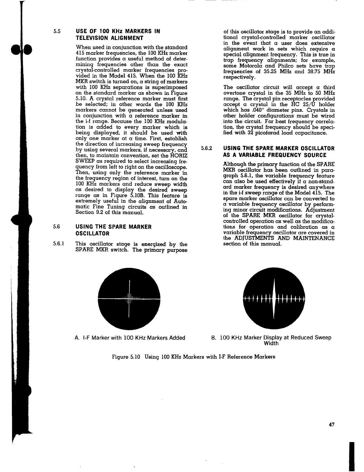
When used in conjunction with the standard
415 marker frequencies, the 100 KHz marker
function provides a useful method of deter-
mining frequencies other than the exact
crystal-controlled marker frequencies pro-
vided in the Model 415. When the 100 KHz
MKR switch is turned on, a string of markers
with IOO KHz separations is superimposed
on the standard marker as shown in Figure
5.10.
A crystal reference marker must first
be selected; in other words the 100 KHz
markers cannot be generated unless used
in conjunction with a reference marker in
the i-f range. Because the 100 KHz modula-
tion is added to every marker which is
being displayed,
it should be used with
only one marker at a time. First, establish
the direction of increasing sweep frequency
by using several markers, if necessary, and
then, to maintain convention, set the HORIZ
SWEEP as required to select increasing fre-
quency from left to right on the oscilloscope.
Then, using only the reference marker in
the frequency region of interest, turn on the
100 KHz markers and reduce sweep width
as desired to display the desired sweep
range as in Figure 5.IOB. This feature is
extremely useful in the alignment of Auto-
matic Fine Tuning circuits as outlined in
Section 9.2 of this manual.
USING THE SPARE MARKER
OSCILLATOR
This oscillator stage is energized by the
SPARE MKR switch. The primary purpose
A. 1-F Marker with 100 KHz Markers Added
5.6.2
of this oscillator stage is to provide an addi-
tional crystal-controlled marker oscillator
in the event that a user does extensive
alignment work in sets which require a
special alignment frequency. This is true in
trap frequency alignments; for example,
some Motorola and Philco sets have trap
frequencies of 35.25 MHz and 38.75 MHz
respectively.
The oscillator circuit will accept a third
overtone crystal in the 35 MHz to 50 MHz
range. The crystal pin receptacles provided
accept a crystal in the HC 25/U holder
which has .040" diameter pins. Crystals in
other holder configurations must be wired
into the circuit. For best frequency correla-
tion, the crystal frequency should be speci-
fied with 32 picofarad load capacitance.
USING THE SPARE MARKER OSCILLATOR
AS A VARIABLE FREQUENCY SOURCE
Although the primary function of the SP ARE
MKR oscillator has been outlined in para-
graph 5.6.1, the variable frequency feature
can also be used effectively if a non-stand-
ard marker frequency is desired anywhere
in the i-f sweep range of the Model 415. The
spare marker oscillator can be converted to
a variable frequency oscillator by perform-
ing minor circuit modifications. Adjustment
of the SP ARE MKR oscillator for crystal-
controlled operation as well as the modifica-
tions for operation and calibration as a
variable frequency oscillator are covered in
the ADJUSTMENTS AND MAINTENANCE
section of this manual.
B. 100 KHz Marker Display at Reduced Sweep
Width
Figure 5.10 Using IOO KHz Markers with 1-F Reference Markers
47
I