TO
OSC!LLOSCOPE
'TO ?LATE OF TO PLATE OF"
! ---- 1ST l·F AMPLIFIER l ±SEC
1
NO l•F AMPCIFIER
I I
I l
: I
I I
I I
I
I
I
I
-------- ---- J
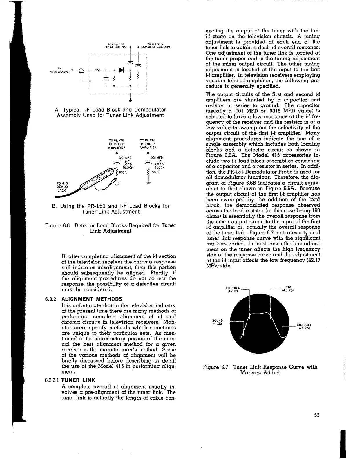
A. Typical 1-F Load Block and Demodulator
Assembly Used for Tuner Link Adjustment
TO PLATE
OF 1ST l·F
AMPLIFIER
tOIMFO.
l·F
LOAD
BLOCK
180'1
TO PLATE
OF 2ND1·F
AMPLIFIER
1001MFO
I
~~tfK
son
B. Using the PR-151 and 1-F Load Blocks for
Tuner Link Adjustment
Figure 6.6 Detector Load Blocks Required for Tuner
Link Adjustment
If, after completing alignment of the i-f section
of the television receiver the chroma response
still indicates misalignment, then this portion
should subsequently be aligned. Finally, if
the alignment procedures do not correct the
response, the possibility of a defective circuit
must be considered.
6.3.2 ALIGNMENT METHODS
It is unfortunate that in the television industry
at the present time there are many methods of
performing complete alignment of i-f and
chroma circuits in television receivers. Man-
ufacturers specify methods which sometimes
are unique to their particular sets. As men-
tioned in the introductory portion of the man-
ual the best alignment method for a given
receiver is the manufacturer's method. Some
of the various methods of alignment will be
briefly discussed before describing in detail
the use of the Model 415 in performing align-
ment.
6.3.2.1 TUNER LINK
A complete overall i-f alignment usually in-
volves a pre-alignment of the tuner link. The
tuner link is actually the length of cable con-
necting the output of the tuner with the first
i-f stage on the television chassis. A tuning
adjustment is provided at each end of the
tuner link to obtain a desired overall response.
One adjustment of the tuner link is located at
the tuner proper and is the tuning adjustment
of the mixer output circuit. The other tuning
adjustment is located at the input to the first
i-f amplifier. In television receivers employing
vacuum tube i-f amplifiers, the following pro-
cedure is generally specified.
The output circuits of the first and second i-f
amplifiers are shunted by a capacitor and
resistor in series to ground. The capacitor
(usually a .001 MFD or .0015 MFD value) is
selected to have a low reactance at the i-f
fre-
quency of the receiver and the resistor is of a
low value to swamp out the selectivity of the
output circuit of the first i-f amplifier. Many
alignment procedures indicate the use of a
single assembly which includes both loading
blocks and a detector circuit as shown in
Figure 6.6A. The Model 415 accessories in-
clude two i-f load block assemblies consisting
of a capacitor and a resistor in series. In addi-
tion, the PR-151 Demodulator Probe is used for
all demodulator functions. Therefore, the dia-
gram of Figure 6.6B indicates a circuit equiv-
alent to that shown in Figure 6.6A. Because
the output circuit of the first i-f amplifier has
been swamped by the addition of the load
block. the demodulated response observed
across the load resistor (in this case being 180
ohms) is essentially the overall response from
the mixer output circuit to the input of the first
i-f amplifier or, actually the overall response
of the tuner link. Figure 6.7 indicates a typical
tuner link response curve with the significant
markers added. In most cases the link adjust-
ment on the tuner affects the high frequency
side of the response curve and the adjustment
at the i-f input affects the low frequency
(42.17
MHz) side.
SOUND
(4L25)
ADJ SNO
(47.25)
Figure 6.7 Tuner Link Response Curve with
Markers Added
53
I