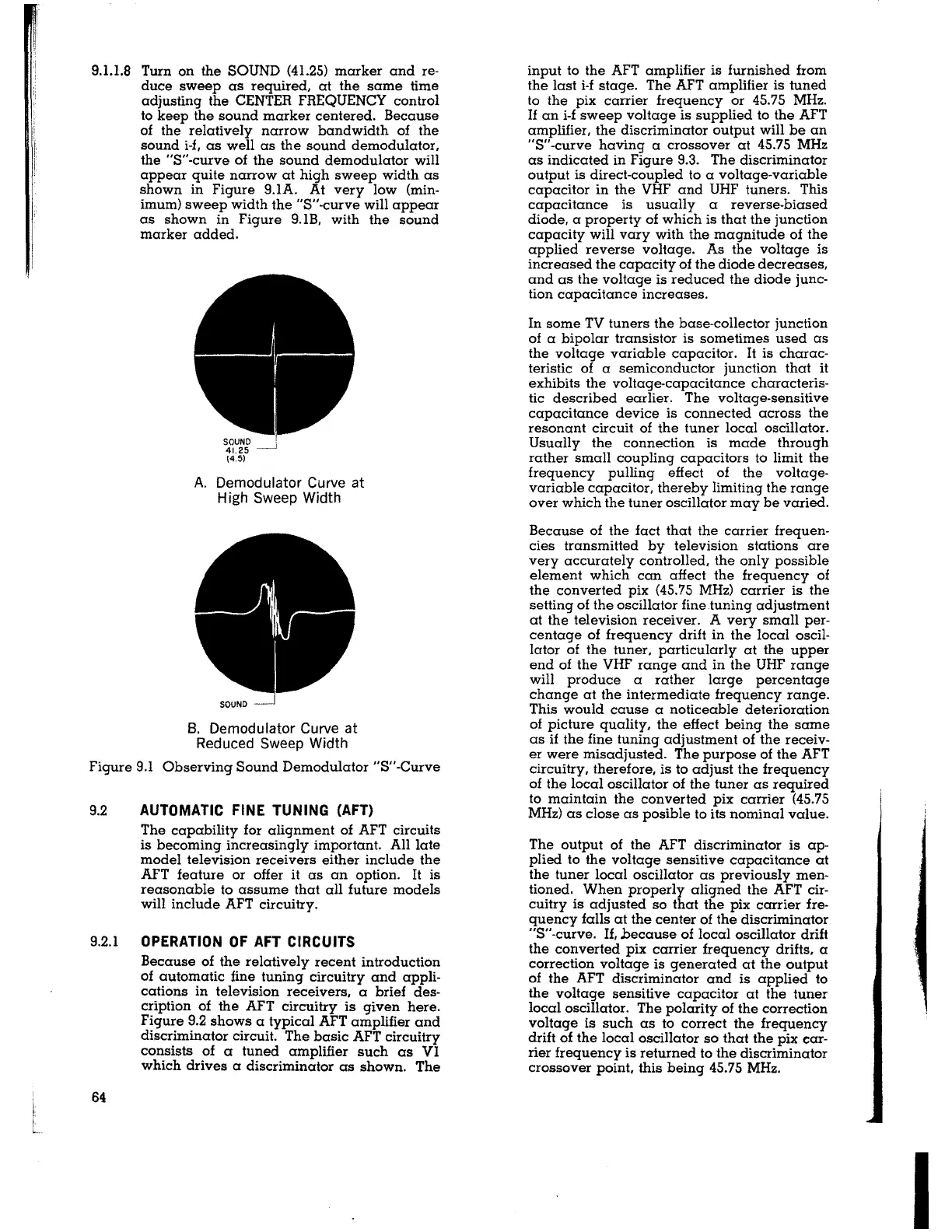
9.1.1.8 Turn on the SOUND (4I.25) marker and re-
duce sweep as required, at the same time
adjusting the CENTER FREQUENCY control
to keep the sound marker centered. Because
of the relatively narrow bandwidth of the
sound i-f, as well as the sound demodulator,
the "$"-curve of the sound demodulator will
appear quite narrow at high sweep width as
shown in Figure 9.lA. At very low (min-
imum) sweep width the "$"-curve will appear
as shown in Figure 9.IB, with the sound
marker added.
A. Demodulator Curve at
High Sweep Width
B. Demodulator Curve at
Reduced Sweep Width
Figure 9.1 Observing Sound Demodulator "$"-Curve
9.2
AUTOMATIC FINE TUNING (AFT)
The capability for alignment of AFT circuits
is becoming increasingly important. All late
model television receivers either include the
AFT feature or offer it as an option.
It is
reasonable to assume that all future models
will include AFT circuitry_
9.2.l
OPERATION OF AFT CIRCUITS
64
Because of the relatively recent introduction
of automatic fine tuning circuitry and appli-
cations in television receivers, a brief des-
cription of the AFT circuitry is given here.
Figure 9.2 shows a typical
AFT amplifier and
discriminator circuit. The basic AFT circuitry
consists of a tuned amplifier such as Vl
which drives a discriminator as shown. The
input to the AFT amplifier is furnished from
the last i-f stage. The AFT amplifier is tuned
to the pix carrier frequency or 45.75 MHz.
If an i-f sweep voltage is supplied to the AFT
amplifier, the discriminator output will be an
"$"-curve having a crossover at 45.75
MHz
as indicated in Figure 9.3. The discriminator
output is direct-coupled to a voltage-variable
capacitor in the VHF and UHF tuners. This
capacitance is usually a reverse-biased
diode, a property of which is that the junction
capacity will vary with the magnitude of the
applied reverse voltage. As the voltage is
increased the capacity of the diode decreases,
and as the voltage is reduced the diode junc-
tion capacitance increases.
In some TV tuners the base-collector junction
of a bipolar transistor is sometimes used as
the voltage variable capacitor.
It is charac-
teristic of a semiconductor junction that
it
exhibits the voltage-capacitance characteris-
tic described earlier. The voltage-sensitive
capacitance device is connected across the
resonant circuit of the tuner local oscillator.
Usually the connection is made through
rather small coupling capacitors to limit the
frequency pulling effect of the voltage-
variable capacitor, thereby limiting the range
over which the tuner oscillator may be varied.
Because of the fact that the carrier frequen-
cies transmitted by television stations are
very accurately controlled, the only possible
element which can affect the frequency of
the converted pix (45.75 MHz) carrier is the
setting of the oscillator fine tuning adjustment
at the television receiver. A very small per-
centage of frequency drift in the local oscil-
lator of the tuner, particularly at the upper
end of the VHF range and in the UHF range
will produce a rather large percentage
change at the intermediate frequency range.
This would cause a noticeable deterioration
of picture quality, the effect being the same
as
if the fine tuning adjustment of the receiv-
er were misadjusted- The purpose of the
AFT
circuitry, therefore, is to adjust the frequency
of the local oscillator of the tuner as required
to maintain the converted pix carrier (45.75
MHz) as close as posible to its nominal value.
The output of the AFT discriminator is ap-
plied to the voltage sensitive capacitance at
the tuner local oscillator as previously men-
tioned. When properly aligned the AFT cir-
cuitry is adjusted so that the pix carrier fre-
quency falls at the center of the discriminator
"$"-curve. If, hecause of local oscillator drift
the converted pix carrier frequency drifts, a
correction voltage is generated at the output
of the AFT discriminator and is applied to
the voltage sensitive capacitor at the tuner
local oscillator. The polarity of the correction
voltage is such as to correct the frequency
drift of the local oscillator so that the pix car-
rier frequency is returned to the discriminator
crossover point, this being 45.75
MHz.
I