70
MAGNAVOX MODEL T933
RF-IF & CHROMA ALIGNMENT
Preliminary Connections
and a -2. 5 volt bias to RF AGC (Point E) on the Chroma
Board.
1.
Adjust Contrast and Brightness controls fully counter-
5. Ground TP202 (Video IF Board) and IF AGC (Point
clockwise and
the Sharpness control to its mid- range
D) on the Chroma Board.
position.
6.
Open the cathode circuit of the Horizontal Output tube.
2. Adjust the Color control to its center position.
7.
Turn the receiver on and set the Volume control for mini-
3. Set the VHF tuner to the highest unused channel. mum volume.
Allow at least 10 minutes warmup time
4.
Connect a -40 volt bias to pin 9 of V707,
-2 volt bias
before proceeding with alignment.
to the junction of R738 & R739 (Bandpass Amplifier),
EQUIPMENT CONNECTIONS
SWEEP GEN. MARKER
REMARKS
FREQUENCY
FREQUENCY
Connect
AM Signal Generator through
4.5MC
----------
Adjust L206 for minimum output.
Slug should be
. 01 Capacitor to Pin 7 of V203.
Con-
400CPS
positioned at point nearest board.
nect scope through Figure 3 to junction
Modulation
of C728
& L717.
Connect IF Sweep Generator and
43MC 47.25MC
Adjust L201 to center marker pip in suckout.
Marker to Tuner Test Point through lOMC Sweep
Adjust R201 for
maximum attenuation.
L201
Figure 4.
Connect scope through
slug should
be at a point near top of coil-. --
Figure 5 to TV chassis.
Connect IF Sweep Generator and 43MC 42.17MC
Adjust the Tuner Converter Plate Coil and T201
Marker through Figure 4 to Tuner lOMC Sweep
47.25MC for maximum gain and response as shown in Fig-
Test Point.
Connect scope through
45. 75MC
ure 7A.
T201 slug should be at point nearest top
Figure 5 to TV chassis.
of can; Tuner Converter Plate Coil slug should
be
at point farthest into coil.
Apply a 41. 25MC CW signal to Tuner
-------- -------- Adjust T204 (Top) and R215 for minimum reading
Test Point. Connect a VTVM to
on VTVM. T204 slug should be at point nearest
TP201.,
top of can.
Connect IF Sweep Generator and 43MC
41.65MC Adjust T204 (Bottom) for maximum gain and
Marker through Figure 4 to Tuner
lOMC Sweep 42.17MC minimum tilt. Adjust T203 to position 42. 17MC
Test Point. Connect scope through
45. 75MC
Marker and T202 to position 45. 75MC Marker
a 10K resistor to TP201. Remove
45.0MC
(see Figure
'iB).
T204 slug should be eositioned
the jumper from TP202.
47.25MC
at point nearest board; T21!2 and T203 positioned
at pomt nearest fop of can.
Recheck 47. 25MC trap.
Recheck 41. 25MC Trap as Outlined Previously
Apply video sweep modulated 45. 75MC 0-SMCSweep 3.0SMC Adjust L717 and T701 (Top
& Bottom) for amplitude
(1. 5V at TP201 on VTVM) to Tuner 3. 58MC and response shown in Figure 8, L 71 7 top slug
Test Point. See Figure 6 for hook- 4.08MC should be positioned at point nearest board.
up. Connect scope through Figure 3
T70I fop slug shouio be positioned at point nearest
to Pin 7 of V710. top
of can; Bottom slug should be positioned
nearest board.
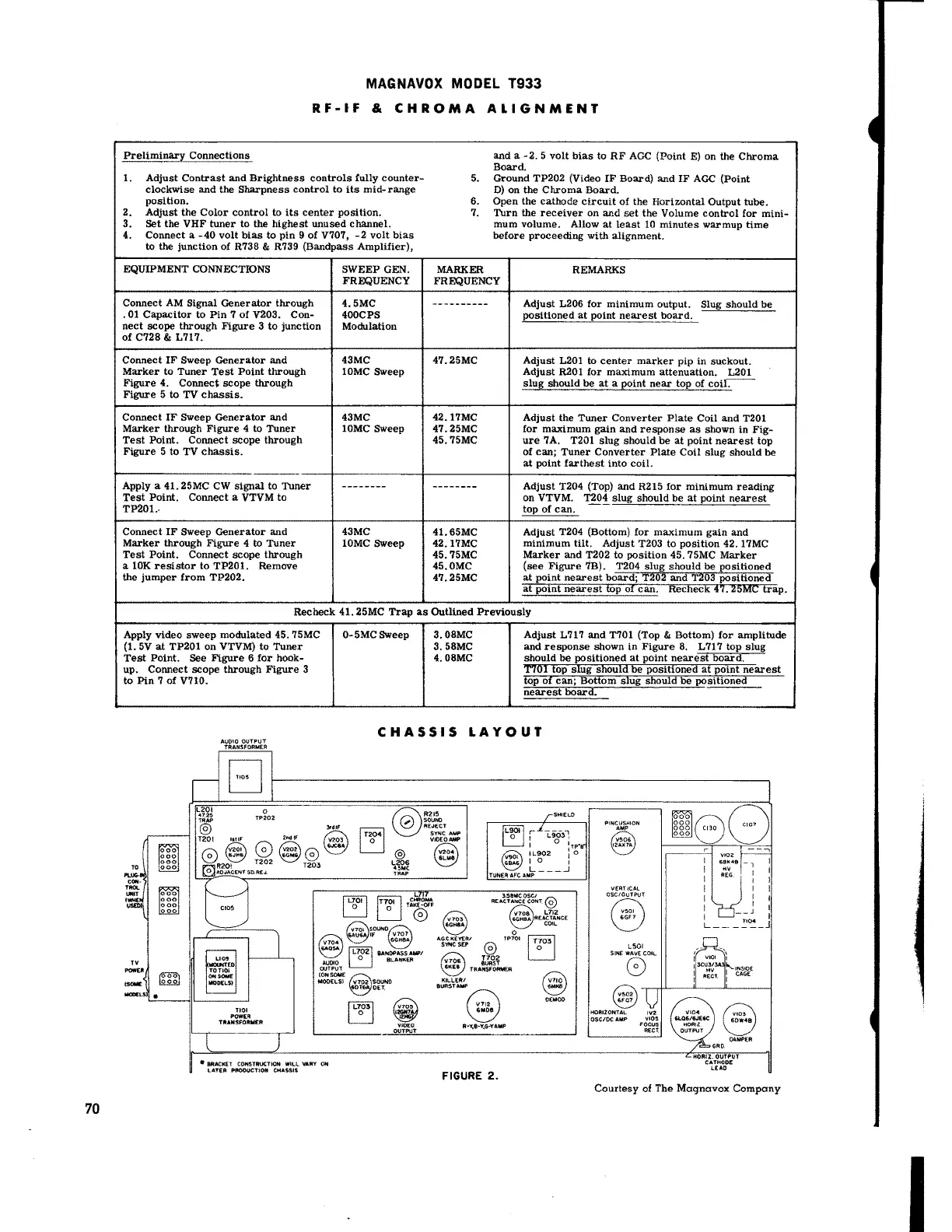
CHASSIS LAYOUT
TV
"""'"
......
L201
.. 'f.25
®
AUDIO OUTPUT
TRANSFORMER
EJ
0
TP:!:02
r;;~ 0
\:::_)~
R20! T202
~AOJAC£NT 50.AEJ.
TIOI
POWER
TRANSFORMER
~,w
2ncllf
~
~~
~©
T203
LI
[!] r,g· 1,i~
@
SOUND
@)
lF V707
6GH8A
~
BANDPASS AW'/
AUOIO
~
BLAP<tKER
CMJTPUT
(ONSOME@
MODELS} V702: SOUNO
60T OET.
1L~·1
~
VIOEO
OUTPUT
• BRACICET CONSTRUCTION WILL VARY ON
LATER PftOOUCTION Ci-iASSIS
St-HELO
~
f"' L.903i
~
I O
1
TP"B"
@
IL902 : 0
I O I
L __ .J
TUNER AFC AMP
REA~~~:fi~T @
V703
6GH8A
V708 L712
6GH8A REACTANC€.
COie
0
A.GC KEY£FI/ TP101
SVNCSEP ©
~
I~~~
~
TRANSFORMER
Kil.LERI
BURSTAW a
~
R-V.8-Y,G-YAMP
FIGURE 2.
~
~
O(MOO
PINCUSHION
AMP
V506
12AX7A
Q
~
HOfllZONTAL
OSC/OC AMP
Courtesy of The Magnavox Company
I