11.1.2.5 Check the dial setting of the f-m receiver.
It should read exactly 88 MHz. Make the
required tracking adjustment for the low
end of the f-m band.
11.1.2.6
A similar check of dial calibration can be
performed at 2 x 47.25 or 94.5
MHz, using
the procedure outlined for 88
MHz.
11.1.2.7 To calibrate the upper end of the f-m band
the 10th harmonic of the 10.7 MHz output of
the Model 415 is used. Place the FUNCTION
switch to the 10.7 MHz
position, keeping the
r-f output cable of the Model 415 connected
to the antenna terminals of the f-m receiver.
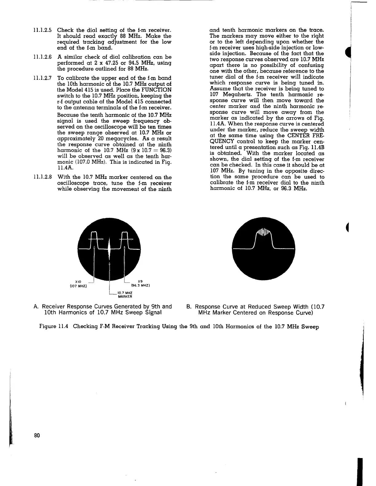
Because the tenth harmonic of the 10.7 MHz
signal is used the sweep frequency ob-
served on the oscilloscope will be ten times
the sweep range observed at 10.7 MHz or
approximately 20 megacycles. As a result
the response curve obtained at the ninth
harmonic of the 10.
7 MHz (9 x 10. 7 = 96.3)
will be observed as well as the tenth har-
monic (107.0 MHz). This is indicated in Fig.
ll.4A.
11.1.2.8 With the 10.7 MHz marker centered on the
oscilloscope trace, tune the f-m receiver
while observing the movement of the ninth
XIO
(107 MHZ)
10.7 MHZ
MARKER
A. Receiver Response Curves Generated by 9th and
10th Harmonics of 10.7 MHz Sweep Signal
and tenth harmonic markers on the trace.
The markers may move either to the right
or to the left depending upon whether the
f-m receiver uses high-side injection or low-
side injection. Because of the fact that the
two response curves observed are 10.7 MHz
apart there is no possibility of confusing
one with the other, because reference to the
tuner dial of the f-m receiver will indicate
which response curve is being tuned in.
Assume that the receiver is being tuned to
107 Megahertz. The tenth harmonic re-
sponse curve
will then move toward the
center marker and the ninth harmonic re-
sponse curve will move away from the
marker as indicated by the arrows of Fig.
11.4A. When the response curve is centered
under the marker, reduce the sweep width
at the same time using the CENTER FRE-
QUENCY control to keep the marker cen-
tered until a presentation such as Fig. 11.4B
is obtained. With the marker located as
shown, the dial setting of the f-m receiver
can be checked. In this case
it should be at
107
MHz. By tuning in the opposite direc-
tion the same procedure can be used to
calibrate the f-m receiver dial to the ninth
harmonic of 10.7
MHz, or 96.3 MHz.
B. Response Curve at Reduced Sweep Width (10.7
MHz Marker Centered on Response Curve)
Figure 11.4 Checking F-M Receiver Tracking Using the 9th and 10th Harmonics of the 10.7 MHz Sweep
80
,--
I
~
I