4.2.6
38
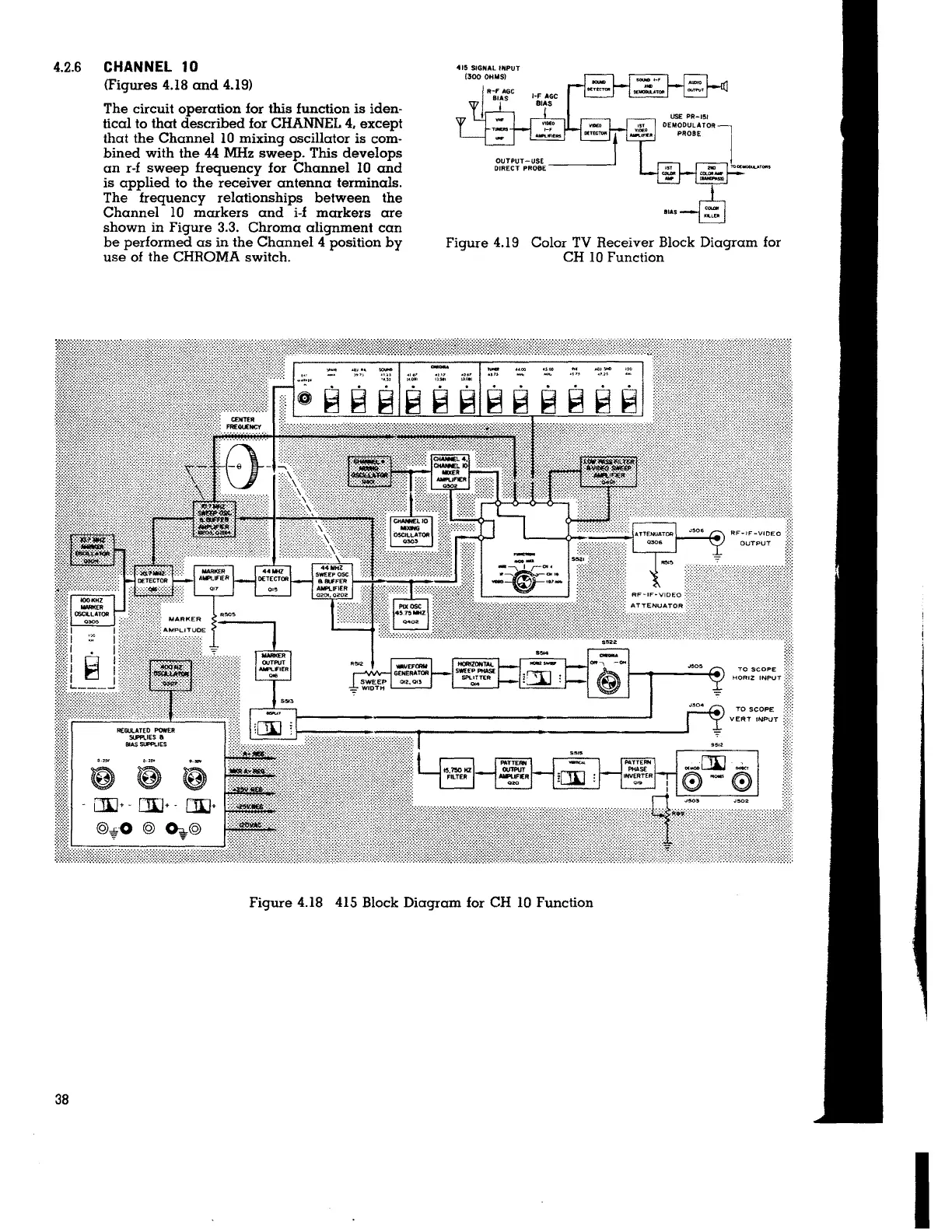
CHANNEL 10
<Figures 4.18 and 4.19)
The circuit operation for this function is iden-
tical to that described for CHANNEL
4, except
that the Channel 10 mixing oscillator is com-
bined with the 44 MHz sweep. This develops
an r-f sweep frequency for Channel IO and
is applied to the receiver antenna terminals.
The frequency relationships between the
Channel 10 markers and i-f markers are
shown in Figure 3.3. Chroma alignment can
be performed as in the Channel
4 position by
use of the CHROMA switch.
415 SIGNAL INPUT
(300 OHMS}
Figure 4.19 Color TV Receiver Block Diagram for
CH 10 Function
TO SCOF>E
HORIZ INPUT
TO SCOPE
Figure 4.18 415 Block Diagram for CH IO Function
I