Physical Interface AW00123409000
90 Basler ace USB 3.0
5.10.3 Measured Propagation Delays
The measured propagation delays reported in this section (see Table 26 and Table 27) are likely to
be near-minimum values related to "slow" edges.
The measured propagation delays were derived from a camera production lot of 2000 cameras and
are only valid for the specific camera operating conditions listed below. The specific camera
operating conditions were only chosen as an example. No inferences can be made for
propagation delays in different operating conditions.
Specific operating conditions:
Housing temperature: +25 °C.
Load resistance: R
L
= 170 Ω
I/O supply voltage: U
S
= 5 VDC
For the graphical illustration of propagation delays, see Figure 46 and Figure 47.
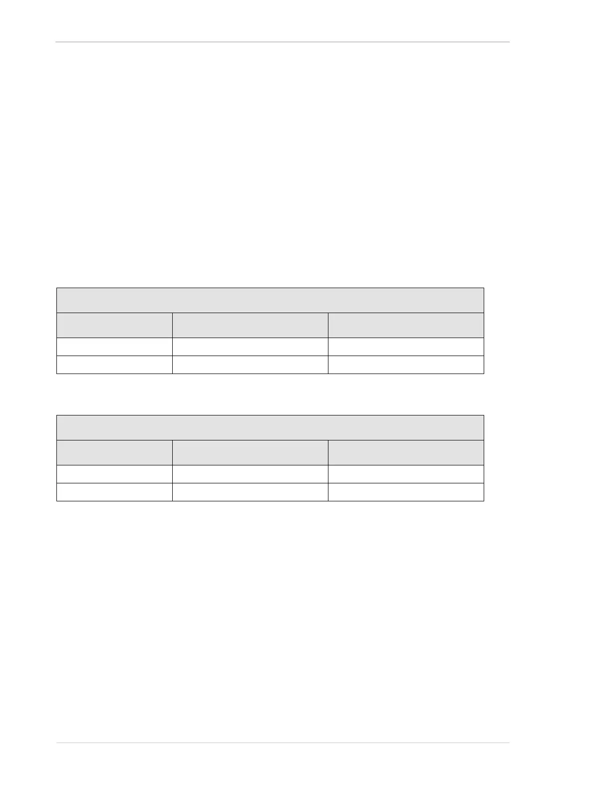
Propagation Delays for Inputs
Fast Edge Slow Edge
Opto-isolated input 4.5 - 7.5 µs (rising edge) 19 - 28 µs (falling edge)
Direct-coupled GPIO IN <0.5 µs (falling edge) <1 µs (rising edge)
Table 26: Propagation Delays for the Camera Inputs (+25 °C, R
L
= 170 Ω, U
S
= 5 VDC)
Propagation Delays for Outputs
Fast Edge Slow Edge
Opto-isolated output 3 - 6 µs (falling edge) 27 - 38 µs (rising edge)
Direct-coupled GPIO OUT <0.5 µs (falling edge) <2.5 µs (rising edge)
Table 27: Propagation Delays for the Camera Outputs (+25 °C, R
L
= 170 Ω, U
S
= 5 VDC,
Transition Threshold = 2.0 V)