Specifications, Requirements, and Precautions AW00123409000
44 Basler ace USB 3.0
1.7 Mounting Instructions
To ensure optimum alignment of the camera when mounting the camera in your system, you must
follow a certain tightening sequence when tightening screws.
Depending on whether you use M2 or M3 screws, a different tightening sequence applies.
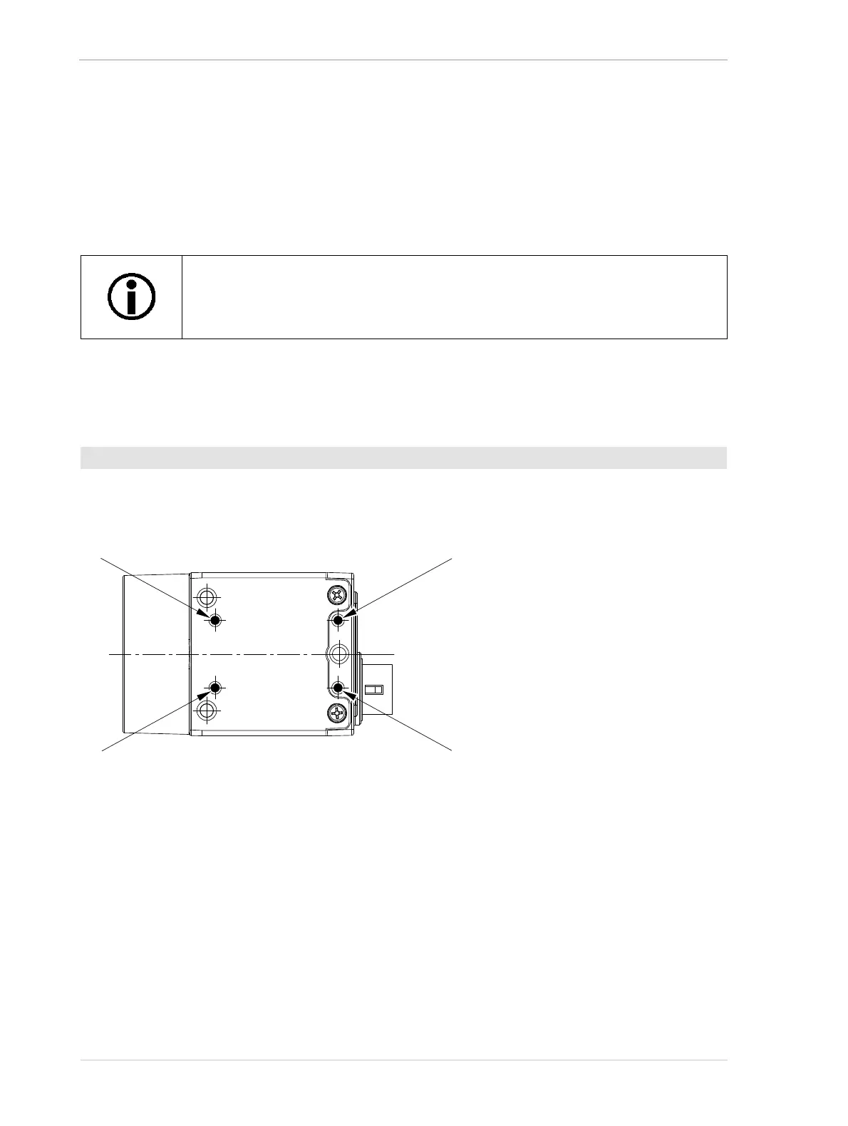
1.7.1 Tightening Sequence When Using the M2 Screws
1. Tighten the screws for the mounting screw holes (a) in Figure 30.
2. Tighten the screws for the mounting screw holes (b) in Figure 30.
Fig. 30: Designations of the Mounting Screw Holes for the M2 Screws.
The tightening sequences are illustrated in Figure 30 and Figure 31 for cameras
with C-mounts. However, the tightening sequences apply equally to cameras with
CS-mounts.
To tighten the M2 screws: