Physical Interface AW00123409000
74 Basler ace USB 3.0
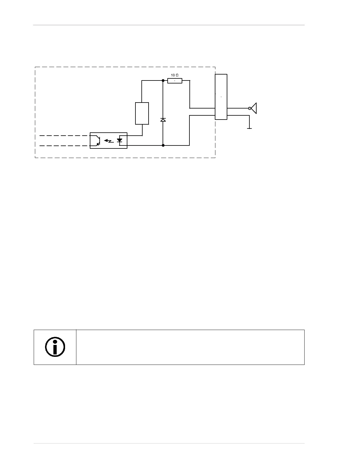
As an example, the use of a TTL or CMOS logic gate in the external circuit is shown.
For more information about input line pin assignments and pin numbering, see Section 5.2 on
page 68.
For more information about how to use an externally generated frame start trigger (ExFSTrig) signal
to control acquisition start, see Section 6.4 on page 122.
For more information about configuring the input line, see Section 5.11 on page 91.
5.8 Opto-isolated Output (Pin 4/Line 2)
The camera is equipped with one dedicated opto-isolated output line designated as Line 2. The
output line is accessed via the 6-pin connector on the back of the camera (pin 4, see Figure 39).
In addition, the camera has two direct-coupled GPIO lines, Line 3 and Line 4, that can both be used
as output lines. They are described in Section 5.9 on page 77.
The opto-isolated output line has the advantage of being distinctly more robust
against EMI than a GPIO line used as an output. However, when using the opto-
isolated output line, the delays involved are longer than for a GPIO line.
6-pin
Receptacle
1
6
3
4
2
5
Camera
Logic Gate
Current
Limiter
Ground for
Opto-isolated I/O
Fig. 40: Opto-isolated Input Line Schematic with a Typical External Circuit (Simplified)