AW00123409000 Physical Interface
Basler ace USB 3.0 77
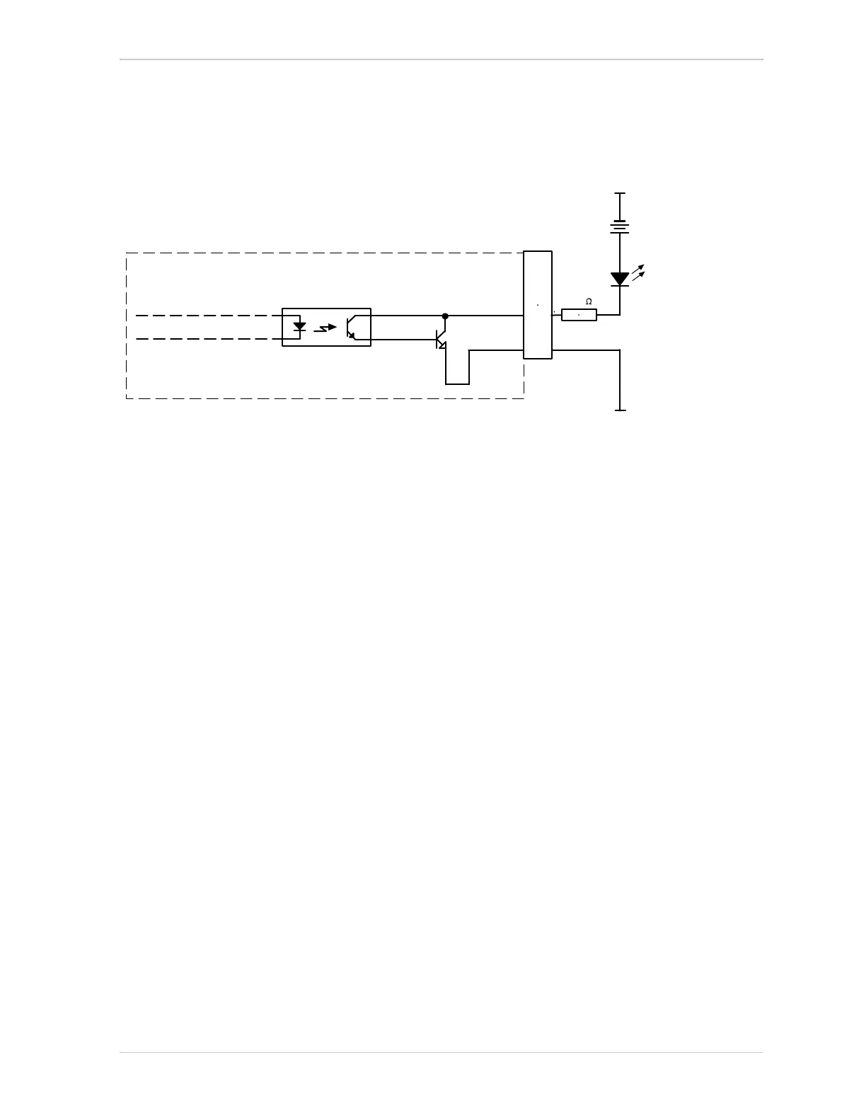
Figure 42 shows a typical circuit you can use to monitor the output line with an LED. In this example,
the voltage for the external circuit is +24 VDC. Current in the circuit is limited by an external resistor.
For more information about output line pin assignments and pin numbering, see Section 5.2 on
page 68.
For more information about the Exposure Active signal, see Figure 6.8.1 on page 161.
5.9 Direct-coupled General Purpose I/O
(GPIO; Pin 1/Line 3, Pin 3/Line 4)
5.9.1 Introduction
The camera has two direct-coupled GPIO lines that are accessed via pins 1 and 3 of the 6-pin
connector on the back of the camera (see Figure 39).
The GPIO lines can be set to operate as inputs to the camera or to operate as camera outputs.
The GPIO lines are designated as Line 3 and Line 4 (see also Section 5.2.1 on page 68).
The direct-coupled GPIO lines are compatible with TTL signals.
The next sections describe the differences in the GPIO electrical functionality when the lines are set
to operate as inputs and when they are set to operate as outputs.
Q1
6-pin
Receptacle
+24
VDC
LED
Output
to You
1
6
3
4
2
5
Camera
2.2 k
Ground for
Opto-isolated I/O
Ground for
Opto-isolated I/O
Fig. 42: Opto-isolated Output Line Schematic with a Typical LED Output Signal at +24 VDC for the External Circuit
(Simplified)