AW00123409000 Physical Interface
Basler ace USB 3.0 105
5.13.2 Line Status for Output Lines
This section informs about the relation between output line status and certain external conditions.
The opto-isolated and the GPIO output lines are considered.
The line status information depends, among others, on whether the output line inverter is disabled
or enabled (Section 5.12.5 on page 100) and on the current setting of the UserOutputValue
parameter (Section 5.12.3 on page 98).
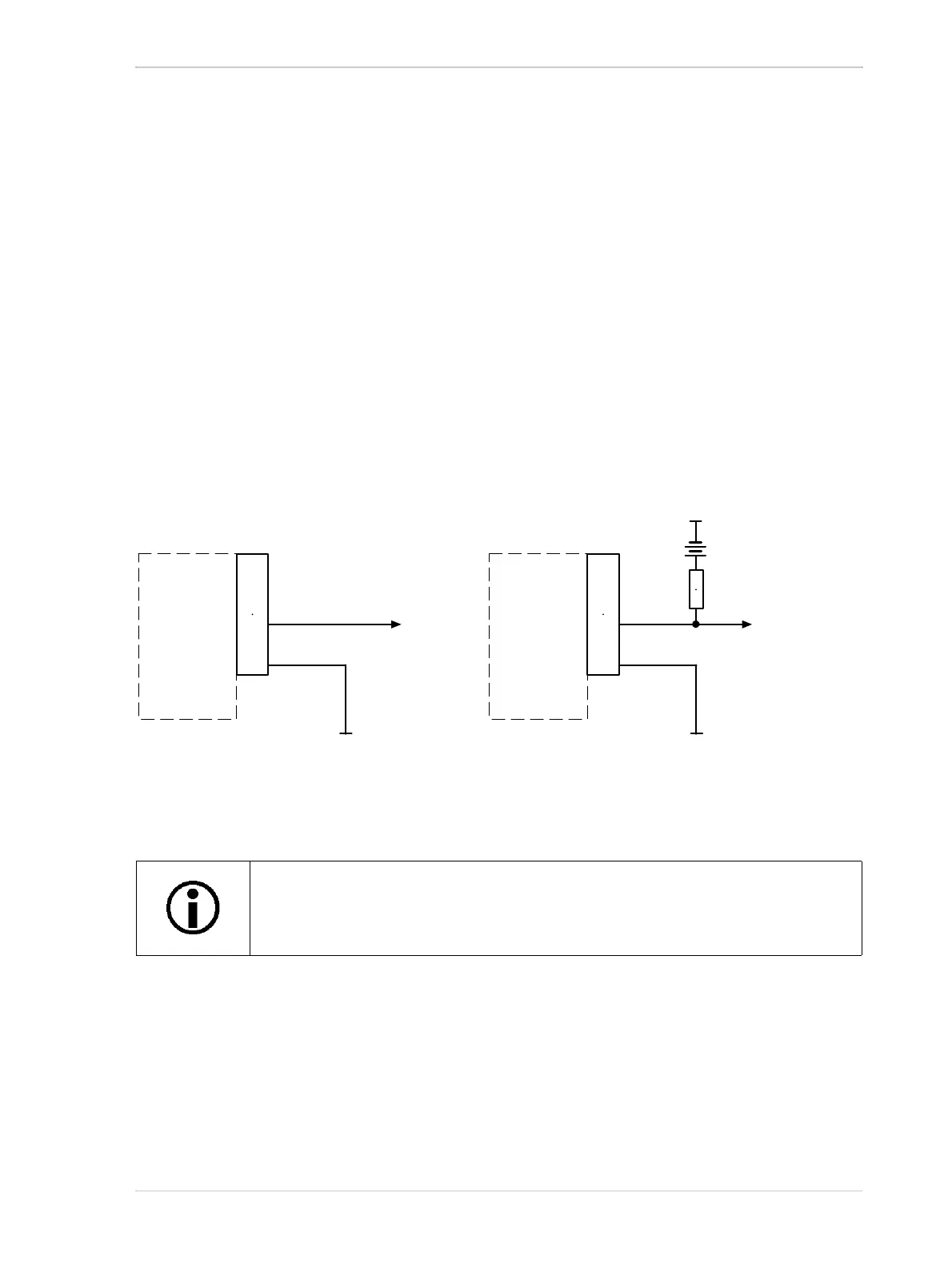
Two types of installation are considered (see Figure 52):
The output line is connected to the external power supply with no external pull-up resistor
involved (A: "external pull-up resistor disconnected"; not useful for the opto-isolated output
line).
The output line is connected to the external power supply via an external pull-up resistor (B:
"external pull-up resistor connected").
Fig. 52: Use of an External Pull-up Resistor With an Output Line: A: No External Pull-up Resistor Connected,
B: External Pull-up Resistor Connected
Make sure the ground for opto-isolated I/O and the ground of the power supply for the opto-isolated
output line are connected to the same ground.
For applicable pins, see Table 20 on page 68, and for line schematics, see Figure 41, Figure 42,
and Figure 45.
The output circuits display open collector circuit behavior. The GPIO lines are,
however, equipped with a weak internal pull up resistor.
6-pin
Receptacle
Voltage
Output
Signal
to You
Camera
6-pin
Receptacle
Voltage
Output
Signal
to You
Camera
Pull-up
Resistor
A
B
Ground for
Opto-isolated I/O
Ground for
Opto-isolated I/O
Ground for
Opto-isolated I/O