Features AW00123409000
296 Basler ace USB 3.0
7.15.3 Auto Function ROIs
Each auto function uses the pixel data from an Auto Function ROI for automatically adjusting a
parameter value, and accordingly, for controlling the related image property. Some auto functions
always share an Auto Function ROI and some auto functions can use their own individual Auto
Function ROIs. Within these limitations, auto functions can be assigned to Auto Function ROIs as
desired.
Each Auto Function ROI has its own specific set of parameter settings, and the parameter settings
for the Auto Function ROIs are not tied to the settings for the ROI that is used to define the size of
captured images (Image ROI). For each Auto Function ROI, you can specify a portion of the sensor
array and only the pixel data from the specified portion will be used for auto function control. Note
that an Auto Function ROI can be positioned anywhere on the sensor array.
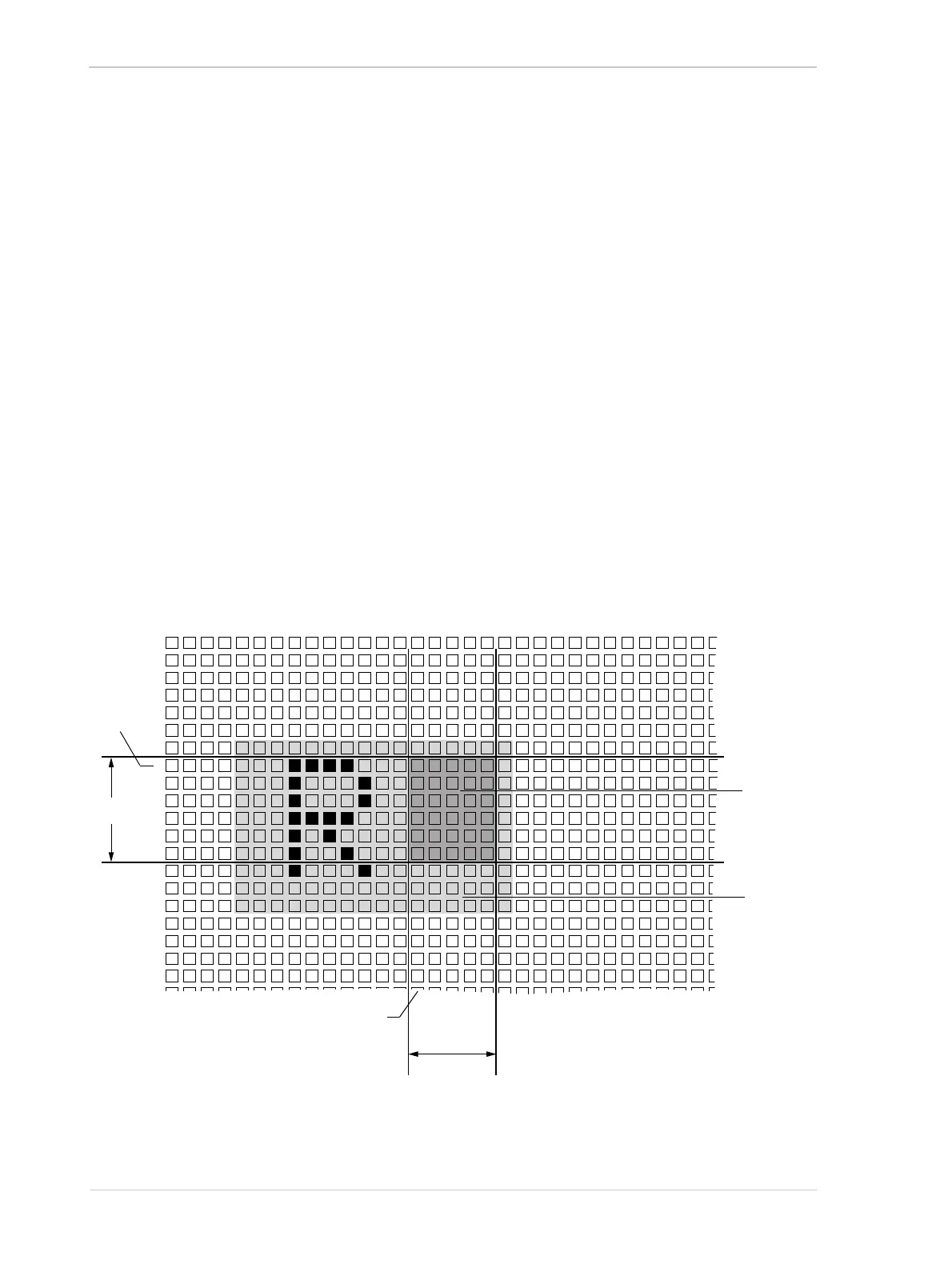
An Auto Function ROI is referenced to the top left corner of the sensor array. The top left corner of
the sensor array is designated as column 0 and row 0 as shown in Figure 110.
The location and size of an Auto Function ROI is defined by declaring an X offset (coordinate), a
width, a Y offset (coordinate), and a height. For example, suppose that you specify the X offset as
14, the width as 5, the Y offset as 7, and the height as 6. The area of the array that is bounded by
these settings is shown in Figure 110.
Only the pixel data from the area of overlap between the Auto Function ROI defined by your settings
and the Image ROI will be used by the related auto function.
01
0
2345678910 11 12 13 14 15 16 17 18 19 20 21 22 23 24 25 26 27 28 29 30
1
2
3
4
5
6
7
8
9
10
11
12
13
14
15
16
17
18
19
Y
Offset
Row
Column
X Offset
Width
Auto
Function
Region of
Interest
Height
Image
Region of
Interest
Fig. 110: Auto Function Region of Interest and Image Region of Interest