Physical Interface AW00123409000
76 Basler ace USB 3.0
Voltages
The following voltage requirements and information apply to the opto-isolated I/O output line (pin 4
of the 6-pin connector; Line 2).
Currents
The leakage current in the "off" state should usually not exceed approximately 60 µA and will
typically be much lower (e.g. approximately 4 µA at 25 °C (+77 °F) housing temperature).
The actual leakage current depends on camera operating temperature and production spread
of electronic components.
The maximum load current allowed through the output circuit is 50 mA.
There is no specific minimum load current but you need to consider several facts:
the leakage current will have stronger effect when load currents are low
the propagation delay of the output increases as load currents decrease
higher-impedance circuits tend to be more susceptible to EMI
higher currents yield higher voltage drop on long cables.
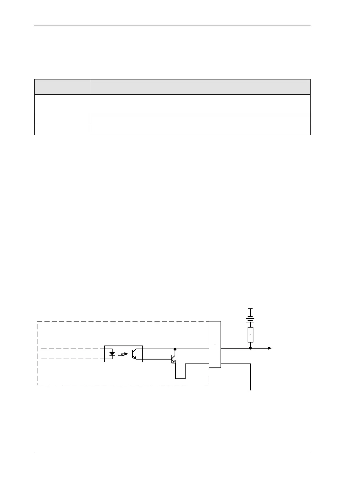
Figure 41 shows a schematic for the opto-isolated output line.
.
Voltage Significance
+30.0 VDC Absolute maximum.The absolute maximum must never be exceeded. Otherwise, the
camera can be damaged and the warranty becomes void.
+3.3 to +24 VDC Safe operating I/O output supply voltage range.
< +3.3 VDC The I/O output can operate erratically.
Table 22: Voltage Requirements and Information for the Opto-isolated Output Line
Q1
6-pin
Receptacle
+3.3 to +24
VDC
Voltage
Output
Signal
to You
1
6
3
4
2
5
Camera
Ground for
Opto-isolated I/O
Ground for
Opto-isolated I/O
Fig. 41: Opto-isolated Output Line Schematic with a Typical Voltage Output Circuit (Simplified)