EasyManua.ls Logo

Bayrol PoolManager PRO - Service Messages

Bayrol PoolManager PRO
94 pages
Print Icon
To Next Page IconTo Next Page
To Previous Page IconTo Previous Page
Loading...
18
46
The following figure shows the internal wiring on the alarm relay. All
connections shown are run internally as conducting paths.
1
Fuse F3 (4 A slow)
2
230 V~ phase L
F
for the alarm relay and the add-on
functions (secured with 4 A)
The terminal block [25] for the alarm relay is set up as follows:
Terminal
Function
b
Working contact
a
Centre contact
L
F
Supply phase 230 V~ for alarm relay and add-on
functions. Can be bridged to the centre contact in
order to control 230 V~ devices.
The following figure schematically shows the connection of a 230 V~
alarm device on the alarm relay.
1
Alarm device 230 V~ (e.g. lamp)
2
Wire bridge in the terminal box from phase L
F
to centre
relay contact a
INFO
Connection of neutral conductor N and PE
An alarm device's neutral conductor N and protective
earth PE can be connected to the N
F
and PE terminal
blocks as shown in the figure.
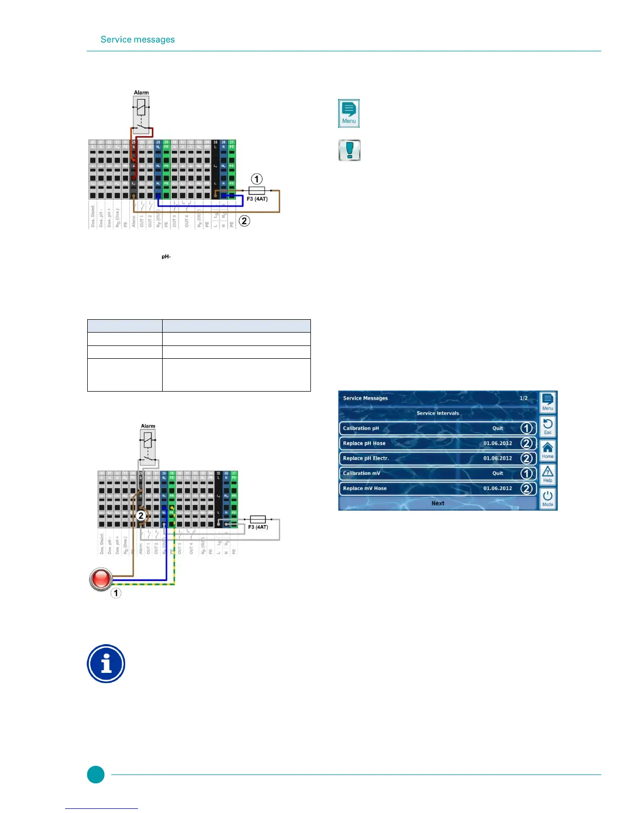
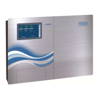
When using the alarm relay as a volt-free switch, the wire bridge (2) is
omitted and the connection is realised on terminal blocks [25a] and
[25b].
18 Service messages
The menu Service Messages is called up as follows:
Menu hotkey
Service Messages
The function Service Messages facilitates targeted planning of certain
service processes:
Calibration (pH, mV, Cl or Br, T)
Recommended interval: 1 month
Electrode replacement (pH, mV, Cl or Br, T)
Recommended interval: 12 months
Hose replacement on the dosing pump (pH, mV, O2, Cl)
Recommended interval: 12 months
A time interval in [months] can be defined for each service process in
the sub-menu Service Intervals. After the configured period of time has
passed, PoolManager
®
will automatically provide a reminder that the
planned service process is due.
The default setting for all service intervals is 0 months, i.e. inactive. In
order to activate the function, an interval of 1...60 months has to be set
for the service processes desired. Resetting to 0 months will
deactivate the service message again.
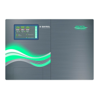
In the menu Service Messages, all planned service processes are
shown along with their due date. If needed, the planned date
calculated by PoolManager
®
can be modified manually.
The service processes are displayed in the menu as follows:
1
These service messages are already due. Therefore, an
acknowledgement button (“Quit”) is displayed.
Pressing the acknowledgement button will reschedule the
process and the newly calculated due date will be
displayed.
2
These service messages are not yet due.
Therefore, the due date is displayed.

Table of Contents

Related product manuals