26.4 Electrical connection
Required user qualification:
ELECTRICAL SPECIALIST
Electrical connection of filter pump control may only be
performed by an ELECTRICAL SPECIALIST as
defined in the chapter User qualification.
Do not exceed the maximum currents
Do not exceed the maximum permissible electrical
currents for each individual relay switch output (max.
4 A) and for the sum of all relay switch outputs being
used in 230 V~ configuration (in sum, also max. 4 A)
Please also refer to the Chapter 230 V~ Power
supply.
The connection options already described for universal switch outputs
can be used for connecting a conventional filter pump; see Universal
switch outputs
connection options.
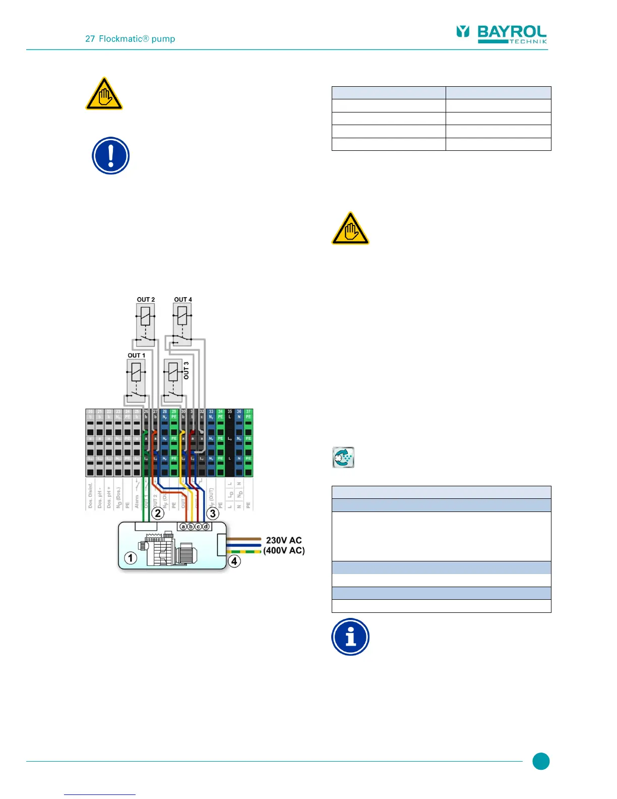
The connection of a variable filter pump is shown schematically in the
following figure.
Volt-free control input for on / off (optional)
Volt-free control inputs to select the operating mode
Volt-free control input for normal mode
Volt-free control input for eco mode
Volt-free control input for increased mode
Joint contact for all volt-free control inputs
External power supply for the filter pump 230 V~
(or 400 V~)
The following Allocation of inputs and outputs is required in the menu
for the connection schematic shown in this figure:
Relay output 'Filter pump on/off'
Relay output 'normal mode'
Relay output ‘increased mode'
27 Flockmatic
®
pump
27.1 Safety information
Required user qualification:
TRAINED SPECIALIST or
ELECTRICAL SPECIALIST
Connection, configuration, and start-up of Flockmatic
®
pump control may only be performed by a TRAINED
SPECIALIST or an ELECTRICAL SPECIALIST as
defined in the chapter User qualification.
27.2 Overview
PoolManager
®
offers the option of connecting and controlling a
Flockmatic
®
pump.
PoolManager
®
Flockmatic
®
control additionally offers the following
options:
Reducing Flockmatic
®
dosing rate
Blocking flock dosing in the event of missing flow
Multiple flexibly programmable timers
Optional level monitoring via a switch input
27.3 Menu Flockmatic
®
pump
The configuration menu for Flockmatic
®
control is called up with the
following icon:
Flockmatic
®
pump
The following settings are available:
Flockmatic
®
mode of operation
Selection of operating mode:
Inactive (Flockmatic
®
control not used)
Off (Flockmatic
®
used, but turned off)
On
Timer
Basic settings for Flockmatic
®
control.
Allocation of a relay switch output
Flockmatic
®
control can only be activated if you have
allocated a relay switch output to it beforehand in the
Basic configuration menu.