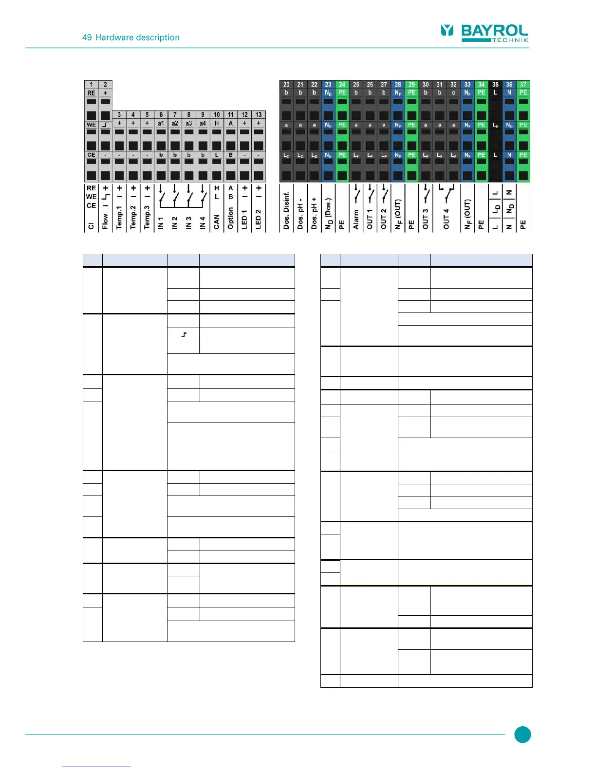
49.4.2 Connection terminals
49.4.2.1 Connection terminals of low voltage
Potentiostatic chlorine
measurement
(Analyt and
PoolManager PRO
only)
Reference electrode
(Ag/AgCl)
Counter electrode (platinum)
Flow switch
(inductive proximity
switch
"OMRON")
During flow, the signal output
is switched to GND
Temperature inputs
1 / 2 / 3
Temp. 1 / 2 0..50°C (820..1200Ω)
Temp. 3 0..75°C (820..1400 Ω)
PT1000
KTY83
KTY16-6
(Parallel resistance 2kΩ required!)
Universal switch
inputs
IN 1 / IN 2 / IN 3 / IN 4
For connecting potential free external
switches or switch contacts.
IN 1 can optionally be used for flow
monitoring.
These terminals are connected
with expansion plugs and
reserved for future functions.
5V with 50Ω series resistance
For connecting LEDs for lighting effects
(optional)
49.4.2.2 Connection terminals for 230VAC
Disinfection
pH-
pH+
Relay working contact
(Dosing output)
Phase 230V~ for dosing outputs
Potential free switch contact between a and b.
Wiring bridge from L
D
to a
230V~ on working contact b
Neutral conductor
N
D
for dosing
outputs
Neutral conductor N
D
is not internally connected
with neutral conductors N
F
and N!
All PE terminals are connected internally
Relay switch
outputs for add-on
functions
OUT 1 / OUT 2 /
OUT 3 / OUT 4
Phase 230V~ for alarm relay
and add-on functions
Potential free switch contact between a and b.
Wiring bridge from L
F
to a
230V~ on working contact b
Relay switch output
OUT 4
Resting contact
OUT 4 inactive Contact a-c closed
Neutral conductor
N
F
for alarm relay
and add-on
functions
Neutral conductor N
F
is internally connected
with neutral conductor N, but not with neutral
conductor N
D
!
All PE terminals are connected internally
PoolManager
®
supply, alarm relay,
and add-on functions
(L
F
fused with 4AT)
Input neutral
conductor
230V~
PoolManager
®
supply, alarm relay,
and add-on functions
All PE terminals are connected internally