The following terminal blocks are allocated to the relay switch outputs:
c = Resting contact
b = Working contact
Each terminal block is set up as follows:
Rest contact (for OUT 4 only)
Supply phase 230VAC for add-on functions.
Can be bridged to the centre contact if needed in
order to control 230VAC devices.
25.4.1 Connection options
Permissible total current exceeded
in 230 V~ applications
For all 230 V~ switch outputs using PoolManager’s
®
internal 230 V~ supply (bridge from L
F
to centre contact
a), the total current must not exceed 4A in total.
The phase L
F
for supplying the add-on functions is
secured with 4 AT (F3 OUT).
Potential consequence:
Burning of conductor paths in PoolManager
®
Ensure that the permissible total current is never
exceeded.
If high currents are needed, then the voltage supply
has to be external.
Please also refer to the Chapter 230 V~ Power
supply.
Exceeding the permissible switching current
or the permissible contact voltage
The electrical current must not exceed 4A per switch
output. The maximum permissible switching contact
voltages are 230 V~ or 30 V DC.
Potential consequence:
Burning of conductor paths in PoolManager
®
Ensure that permissible currents and permissible
voltages are never exceeded.
If applicable, secure the electrical circuits externally
in accordance with applicable stipulations.
If higher currents or voltages are needed, then an
external electrical power switch has to be used.
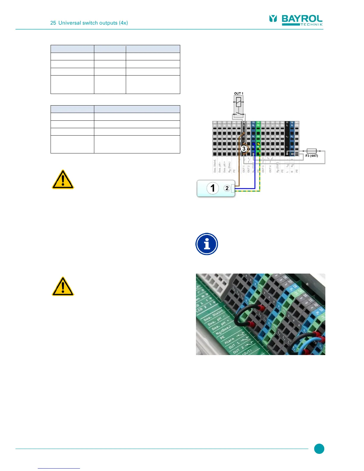
25.4.1.1 Control of an external system via 230V~ mains supply
A 230 V~ unit is connected between neutral conductor N (blue) and
phase L (brown) of the power supply, between which there is a voltage
of 230 V~ (AC voltage). Additionally, there is generally also a
protective earth connection (yellow/green).
Should a unit of this kind be controlled via a PoolManager’s
®
universal
switch output, then it has to be connected as follows (Example for
switch output OUT 1):
External system to be controlled
External system’s 230 V~ power supply
Wire bridge in the terminal box from phase L
F
to centre
relay contact a
Connection of neutral conductor N and PE
The controlled external system's neutral conductor N
and protective earth PE can be connected to the N
F
and PE terminal blocks as shown in the figure.
Wire bridge in the terminal box from phase L
F
to centre relay contact a