49.6.2 Connecting the flow switch
Also see the section Flow monitoring.
Connecting a reed contact
If a simple reed contact or other potential free contact is
being used instead of an the inductive proximity switch,
then it can be connected to the terminals [2 ] and [2
-
].
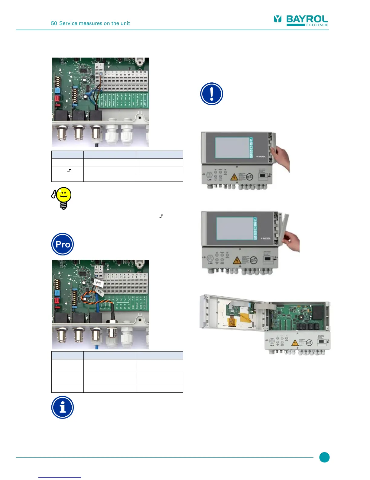
49.6.3 Connection of chlorine measuring cell
This section applies for the model
PoolManager
®
O2 only.
Reference electrode
(Ag/AgCl)
Counter electrode (platinum)
Working electrode (gold)
Electrode connection
RE and CE are connected to a BNC socket via adapter
cable. The chlorine measuring cell's glass electrode is
connected to it. This is a standard redox electrode
containing the reference electrode (RE) and the
counter electrode (platinum round end, CE).
The blue connection cable for the working electrode
(WE) is linked directly with the chlorine measuring cell's
gold electrode.
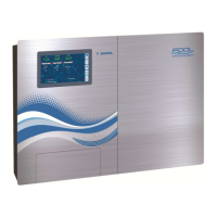
50 Service measures on the unit
50.1 Opening the casing
Open on the right
Never open the casing on the left side, as damage may
otherwise occur.
Always open on the right side!
1. Firmly press the hinge on the right side out and to the right.
2. Remove the cover plate and unhook the hinge on the bottom.
3. Swing the casing cover open to the left.
4. To close the casing, reverse this procedure.
50.2 Opening the terminal box
The terminal box cover is anchored by four screws. Loosen the four
screws and remove the terminal box cover.
When closing, tighten the screws enough that there is a reliable seal.