49.5 Power supply 230V~
PoolManager
®
has three different branches for 230 V~ supply:
230 V~ supply for the PoolManager
®
unit
(L / N / PE, fuse F1 3.15SB)
230 V~ supply for dosing outputs
(L
F
/ N
F
/ PE, fuse F2 2SB)
230 V~ supply for alarm relay and supplement functions
(L
F
/ N
F
/ PE, fuse F2 2SB)
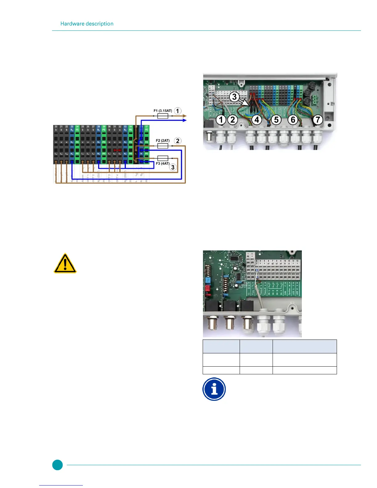
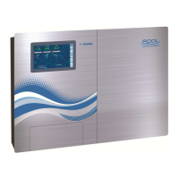
The following figure schematically shows the connections present on
the printed circuit board:
The supply for the PoolManager
®
unit as well as for the alarm relay
and the add-on functions share a mutual power input (L/N). Phase L
for PoolManager
®
is run from the input over via fuse F1. Phase L
F
for
the alarm relay and the add-on functions is run from the input via fuse
F3. Neutral conductors N and NF are connected to each other
internally.
Supply to the dosing outputs is run via a separate power input (L
D
/
N
D
). This input is fused via F2 and does not have an internal
connection to L / L
F
or N / N
F
.
Gaseous chlorine produced from dosing in standing
water if dosing outputs are not locked.
If the flow switch is stuck or experiences other types of
errors, there is a risk of dosing in standing water.
Poisonous chlorine gas can be yielded when sodium
hypochlorite and pH minus come together.
Potential consequence: Death or the gravest
degree of injury,
heavy material damage.
Only run power to input L
D
/ N
D
for the dosing
outputs if circulation is running under voltage
(dosing outputs locked via filter pump).
Connect power input L
D
/ N
D
to the timer that
controls the filter pump, or use the corresponding
outlet on the filter pump.
If PoolManager
®
is controlling the filter pump
directly, then locking automatically occurs
internally.
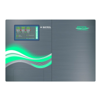
49.6 Standard wiring
(Without add-on functions)
The following figure schematically shows a typical PoolManager
®
connection configuration.
Flow switch [terminal block 2]
Wire bridges from L
D
to a for 230 V~ dosing pumps
Dosing pump disinfection [20]
230 V~ power supply for dosing pumps
[L
D
/ N
D
/ PE], locks via the filter pump!
230 V~ power supply for PoolManager
®
, the alarm relay,
and add-on functions [L / N / PE]
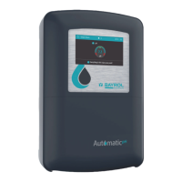
49.6.1 Connecting a temperature sensor
Also see the section Temperature measurement.
Cable colour
(standard PT1000 sensor)
Extended temperature measurement range for
Temp. 3
Temperature input Temp. 3 is designed for
temperatures from 0...75 °C and is therefore
particularly well suited for connection with a solar
sensor.
Temp. 1 and Temp. 2 are designed for 0...50 °C.