Installation and connection
30
MK2430_D00129_02_M_XXEN/09.2019
4.3.4.2 MK2430-11
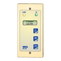
The MK2430-11 alarm indicator and test combination provides additional terminal
strips for the 12 digital inputs and one optional relay output.
Also refer to „Settings menu 4: Digital inputs (MK2430-11 only)“ on page 62.
4.4 Examples for BMS bus connection and addressing
IN1…IN12 Digital inputs 1…12
0 (IN1…4) Common connection "0" for digital inputs 1…4
0 (IN5…8) Common connection "0" for digital inputs 5…8
0 (IN9…12) Common connection "0" for digital inputs 9…12
21, 22, 24 Relay output (option)
NC No function (not connected)
Missing or incorrectly installed terminating resistors (e.g. in the middle of
the bus) will cause bus instability. Please also note the information in the
"BMS bus" operating manual.
 Loading...


