Antennas
15-5
always be mounted upright with its angled corner at the
bottom.
7. Refit the front cover by pressing its sides into the base.
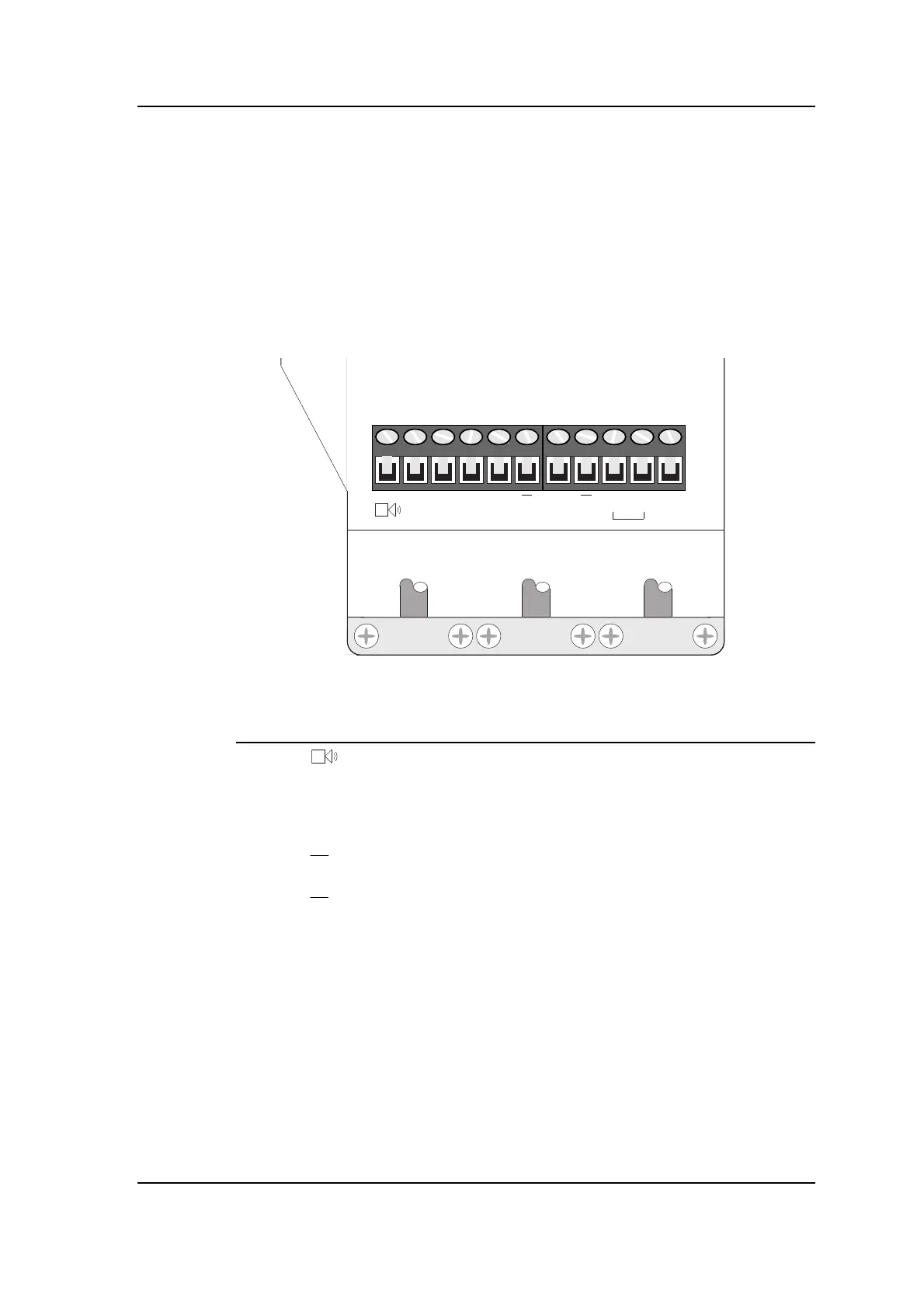
Connecting the 280 Reading Head
The connector on the 280 Reading Head is laid out as follows:
Viewed from front
V
+
D
1
D
2
D
3
R
X
T
X
TXR
X
LK TX
C
The pin descriptions are as follows:
Pin Label Cable colour* Description
1 Orange Horn (on 280 Mk2)
2 V+ Brown +ve supply to LED anodes (and horn on Mk2)
3 D1 Red Red LED cathode
4 D2 Yellow Amber LED cathode
5 D3 Green Green LED cathode
6 RX Black/White Receive line
7
RX Black/White Receive line
8 TX Black/Red Transmit line
9
TX Black/Red Transmit line
10 LK Not used
11 TXC Not used
*
This column shows the recommended cable colour for each function
when you use 812 cable.
Notes:
• The cable screens should be connected at the Controller only.
At the Reading Head they should be cut back and insulated.
See the chapter on “Earthing and screening”.
• A break-out box can be used between the main feeder cable(s)
and the Reading Head. See the chapter on “Cables” for details.