4922 Dual PINpad Data Adapter and 4988 PINpad Data Converter
6-3
Connecting the PINpad to the 4988 PINpad Data Converter
The 4988 PINpad Data Converter should be mounted inside or close
to the PINpad. Connect the two as shown in the following table.
4988
PINpad CONN2
No connection SCR - connect cable screen to 4988 only, not to PINpad
row1 X1
row2 X2
row3 X3
row4 X4
column1 Y1
column2 Y2
column3 Y3
column4 Y4
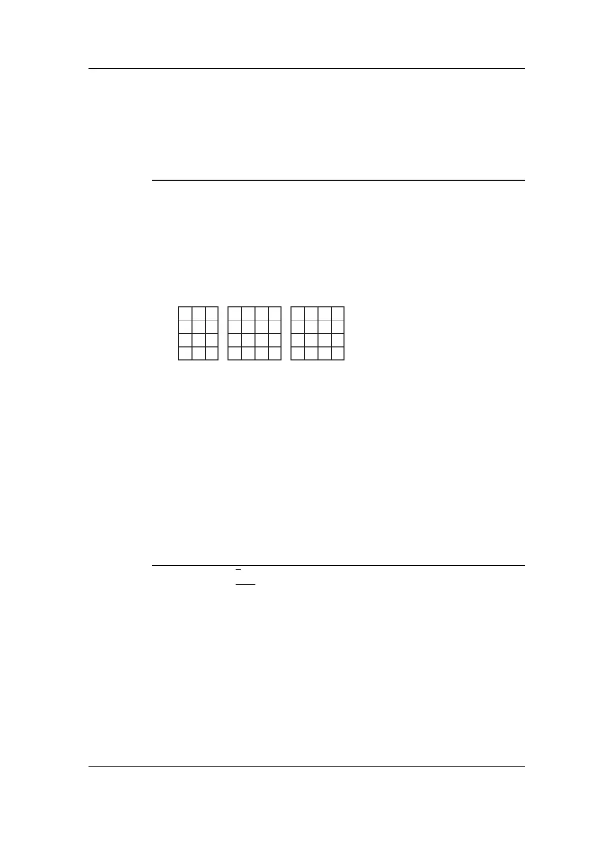
456
CE
1230
7
89
AB
DF
Type 2
123
456
789
✱ 0#
Type 1
123
456
789
0FE
A
B
C
D
Type 3
X1X2 X3
Y4
Y3
Y2
Y1
X1X2 X3 X1X2 X3X4 X4
Connecting the PINpad LEDs
The 4988 PINpad Data Converter Provides four outputs which you
can use to drive indicator LEDs. We recommend that you connect the
two drivers shown in the table below to green and red LEDs. If you
are using a PINpad with LEDs built in then the connections can be
made direct. If you are using a PINpad without LEDs then make the
connections to green and red LEDs mounted near the PINpad. You
can use the 272 Remote Indicator for this purpose if you wish. The
outputs are open collector and pull down to 0V when on. You can use
the V+ connection as the common anode.
PINpad or 272 4988 CONN2 Function
green LED E lights when PIN required
red LED
A / E lights when key pressed or fault occurs
+ volts V+ common anode (+ve)
Testing
When you have connected the 4922 Dual PINpad Data Adapter to one
or two 4988 PINpad Data Converters, power up the Controller and
look at the amber LEDs on the 4922 labelled D6 and D7. If the
connections are correct, the corresponding LED should be flashing -
D7 for A, D6 for B. If the LED is not flashing then you must check
your wiring.