4101-2 Controller Installation Handbook
8-4
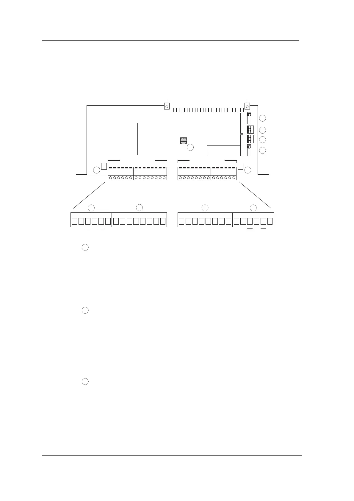
Connectors, jumpers, switch and LEDs
The following diagram shows the position of connectors, jumpers,
rotary switch and LEDs on the Comms module.
A TXD TXD SE TXD CTSRTSDCDDTR SE Scr RXDTXDCTS RTS Scr BDCDDTR SE RXDRXDTXD TXD SE 485232 232RXDScr RXDRXD Scr485
5
6 7
8
9
10 11
DownstreamUpstream
1
2
3
4
1
Upstream baud rate selection jumper (JU1): selects the baud
rate for communications upstream of the Comms module
(upstream is labelled A on the Comms module, both on the
connectors and the jumpers).
The baud rate selected applies to both RS232 and RS485,
whichever is selected using jumper 2.
2
Upstream comms links (JU2). The RS485/RS232 link selects
whether communication upstream from the Comms module is
RS485 or RS232. The DIR/DIAL link selects whether the
Comms module is communicating with a modem connected to
a dial-up telephone line for remote site operation (DIAL) or
whether the Comms module is being used normally with a
direct connection (DIR). (The other link, A/B, is currently not
used.)
3
Downstream comms links (JU3). The RS485/RS232 link
selects whether communication downstream from the Comms
module is RS485 or RS232. The DIR/DIAL and A/B links
select the downstream time-out as shown in the following
table: