4253 Input/Output module 16/8 & 4953 I/O Status Display module
7-3
Inputs
The 4253 I/O module provides sixteen inputs, eight of which have
the even address of the slot into which the module is plugged and the
other eight of which have the odd address. Each set of eight is
labelled I1 to I8.
Inputs are monitored with respect to ground (0V).
Each input can be configured in the Software as a supervised input.
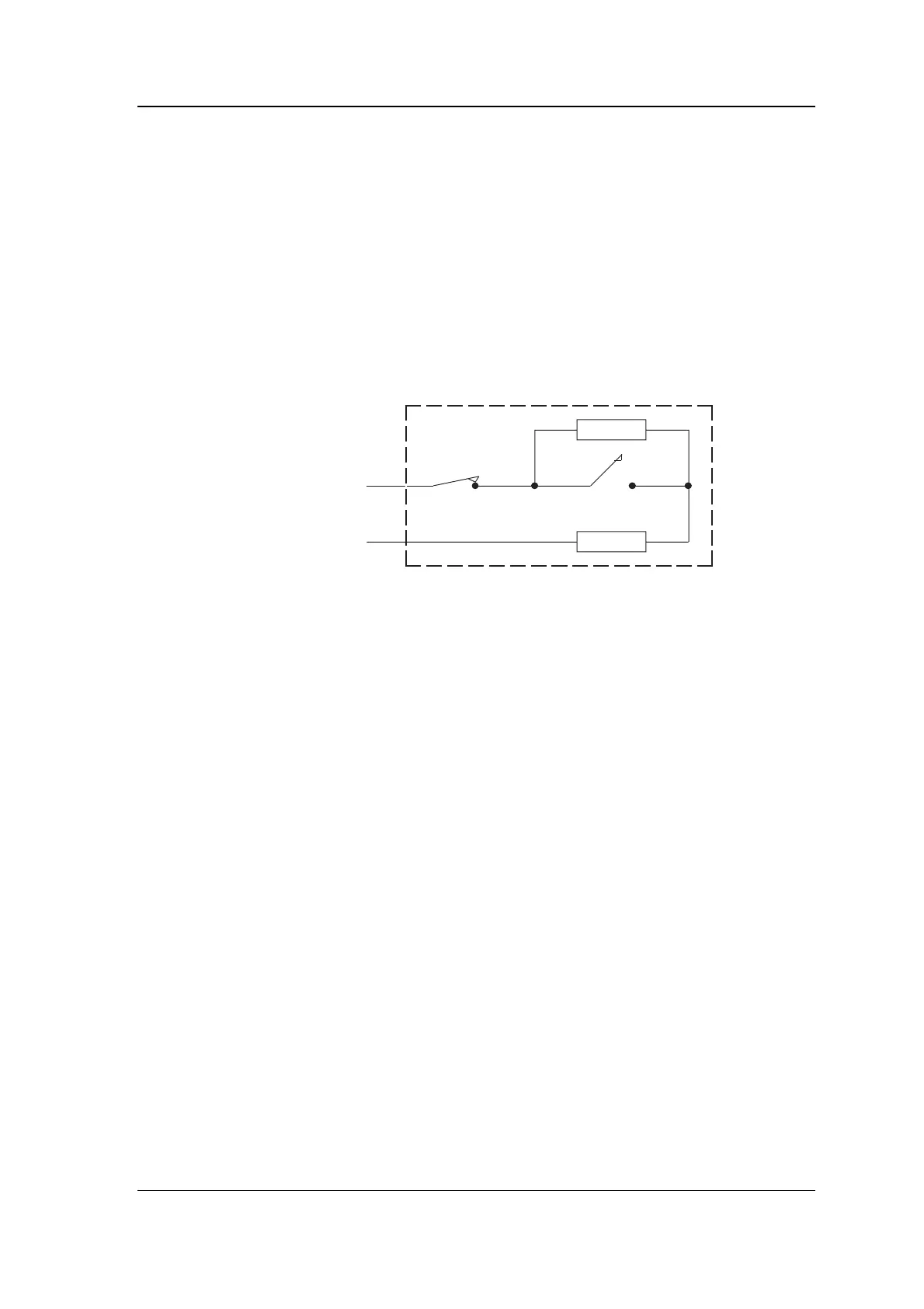
If you wish to use a supervised input it must be wired as shown in
the following diagram.
Aux
0V
5k6
1k8
TS
The switch or relay contact driving the input (labelled S in the
diagram) must be connected via a 1k8Ω 0.25W 5% resistor in series,
and must also have a 5k6Ω 0.25W 5% resistor across it in parallel.
This ensures that the system can tell the difference between a valid
active state and a tamper condition (short or open circuit).
Some devices include a built-in tamper switch (labelled T in the
diagram) which activates when the device is opened or smashed.
Provided this tamper switch is normally closed, its activation will be
detected as a tamper condition. Note: all the components shown
within the dashed box in the diagram must be mounted within the
device's case.
The input wiring described above is suitable for most purposes. If you
have a non-standard application which uses extra components
external to the input you will need to know the voltage switching
thresholds.