4101-2 Controller Installation Handbook
6-2
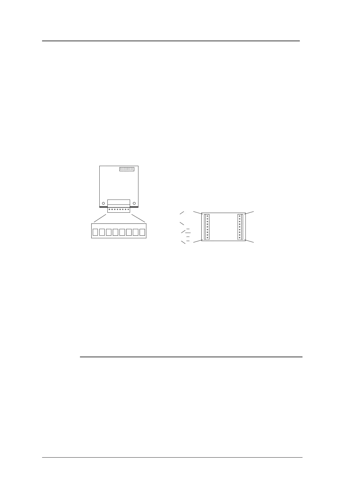
Mounting the 4988 PINpad Data Converter
The 4988 PINpad Data Converter has approximate dimensions
60x35x15 mm. Four holes are provided in the circuit board for
mounting it inside OEM products.
4922/4988 connectors and LEDs
The following diagram shows the position of the connectors and LEDs
on the 4922 Dual PINpad Data Adapter, and the positions of the
connectors on the 4988 PINpad Data Converter.
V+ RA TA RBSCR ØV TB
LEDLED
CONN1
SCR
Y1
Y2
Y3
Y4
X1
X2
X3
X4
SCR
ØV
V+
R
T
E
A/E
O
C
CONN1 CONN2
to
4922
to
PINpad
LED
drivers
Connecting
Connecting the 4922 Dual PINpad Data Adapter to one or
two 4988 PINpad Data Converters
Using a separate 4-core overall screened cable such as Belden 9534
for each 4988 PINpad Data Converter, connect CONN2 on the 4922
to CONN1 on each 4988 as shown in the following table.
4922 4988 (A) 4988 (B)
CONN2 CONN1 CONN1
ØV ØV ØV
V+ V+ V+
RA T -
TA R -
RB - T
TB - R
case* SCR SCR
A is PINpad for “even address” Reader, B is PINpad for “odd address” Reader.
*The cable screens should be connected to the nearest binding post to where the cables enter
the 4101-2 Controller case.
The maximum distance between the 4922 and a 4988 is 300 metres with screened cable.