4230/4232/4235 Communications modules
8-13
Tx and Rx connections from the Controller to the Comms
module must be swapped: TXD/
on the Comms module
go to RXD/
on the motherboards, RXD/
on the
Comms module go to TXD/
on the motherboards.
4. The motherboards are all connected in parallel, TXD/
to
TXD/
, RXD/
to RXD/
.
Connecting the host computer to the Comms module
The computer is usually connected via its serial port directly to the
upstream (CONN2) RS232 connections of the Comms module. COM1:
is usually a 9-way D-type connector.
Module Function Connection
Scr No connection Connect cable screen to Controller case
RXD Receive Data to computer TXD, 9-way: pin 3, 25-way: pin 2
TXD Transmit Data to computer RXD, 9-way: pin 2, 25-way: pin 3
CTS Clear To Send see following diagram
RTS Ready To Send see following diagram
DCD No connection Not used
DTR No connection Not used
SE Signal Earth to computer Signal Earth
9-way: pin 5, 25-way: pin 7
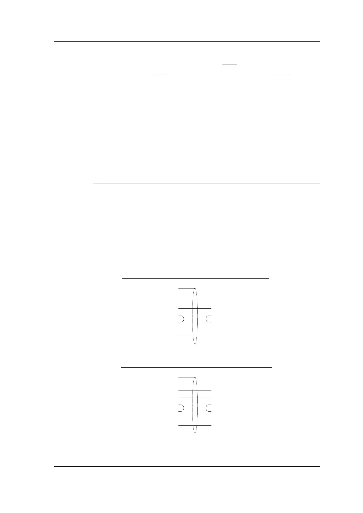
Note: CTS and RTS should be linked together both at the computer
and at the Comms module as shown in the diagrams below.
PC: 9-way COM1:
2 RXD
3 TXD
8 CTS
7 RTS
5SE
Comms module
Connect cable screen
to Controller case
TXD
RXD
RTS
CTS
SE
PC: 25-way COM1:
3 RXD
2 TXD
5 CTS
4 RTS
7SE
Comms module
Connect cable screen
to Controller case
TXD
RXD
RTS
CTS
SE