4101-2 Controller Installation Handbook
3-2
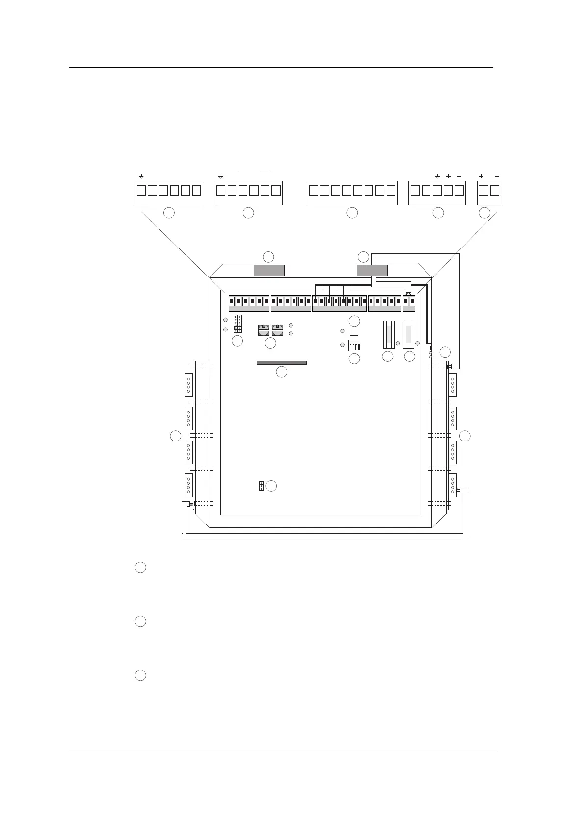
Connectors, switches and LEDs
The following diagram shows the position of connectors, switches and
LEDs in the 4101-2 Controller.
1 2 3 4
RXDTXD CTSRTS 0V RX RX TX TX 0V
POWER
LED
STATUS
LED
TAMPER PSUMON +12 0V
AUX IN AUX OUT
31 2 4 5
66
7
8
9
10
11
12 13
1515
14
LEARN
16
1
RS232 connector (CONN1): for connecting the Controller direct
to the PC. On systems with more than one Controller, CONN1
can be used for connecting the Radio Controlled Clock.
2
RS485 connector (CONN2): for connecting the Controller to the
Communications module and to the other Controllers on a
branch, or to a slave Controller in a two-Controller system.
3
Various status LEDs and tamper switch connector (CONN3):
for connecting the tamper switch, the LEDs on the tamper
switch board, and the mains power fail input from the PSU.
(The two LEDs and the tamper switch are already connected at
manufacture.)