4101-2 Controller Installation Handbook
5-2
Door open monitoring inputs (door open and door forced
functions - DO)
A door monitoring switch (shorted when the door is closed) connected
between DO (the door open input - do not mistake for DØ, the data
input, which is next to the D1 connection on the module) and ØV
provides door open and door forced information.
Cdk
Special connections for Cardkey
TM
.
Connectors, jumpers and LEDs
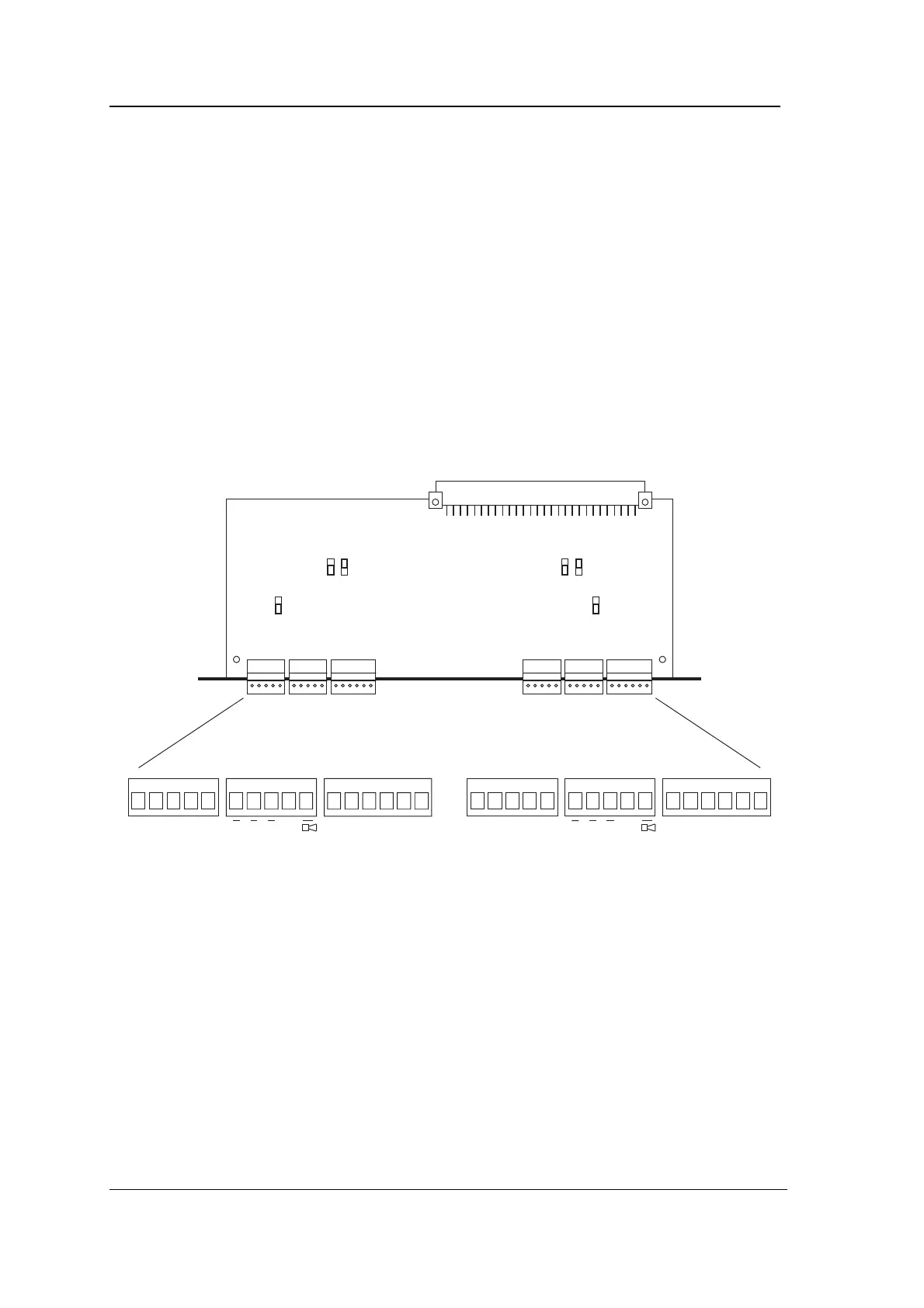
The following diagram shows the position of connectors, jumpers and
LEDs on the 4422 module.
+V ØV D1 DØ Cdk NC Com NO DO ØV EG NC Com NO DO ØV EGRAGVA RAGVA
LED LED
B
A
JU1
B
A
JU2
B
A
JU3
B
A
JU4
B
A
JU5
B
A
JU6
+V ØV D1 DØ Cdk
JU3/JU6
JU3 selects the voltage on the left hand reader’s +V terminal. JU6
selects the voltage on the right hand reader’s +V terminal. The A
position gives 5.0V regulated, 100mA maximum. The B position gives
11.2V regulated, 150mA maximum (but this output may fall to
around 10.5V when the Controller is being powered by battery
backup). The default setting is 5V.
JU2/JU5
JU2 and JU5 configure the left and right reader respectively for
connection to a Wiegand or a Magnetic Stripe reader.
With the jumper in the B position, data is both read and clocked from
DØ and D1 using the edges of the data pulses. This is the position to