4101-2 Controller Installation Handbook
3-4
15
Auxiliary power connectors: for connecting lock strikes and
any other equipment that requires DC power. Connected to
CONN5 at manufacture. 4910 PSU supplies 12V 4A auxiliary
power as standard, or 24V 2A with 12/24V converter fitted.
16
Learn Distributor Code jumper: UP for LEARN DC, DOWN for
normal operation
Motherboard LEDs (see section later in this chapter).
Module slots
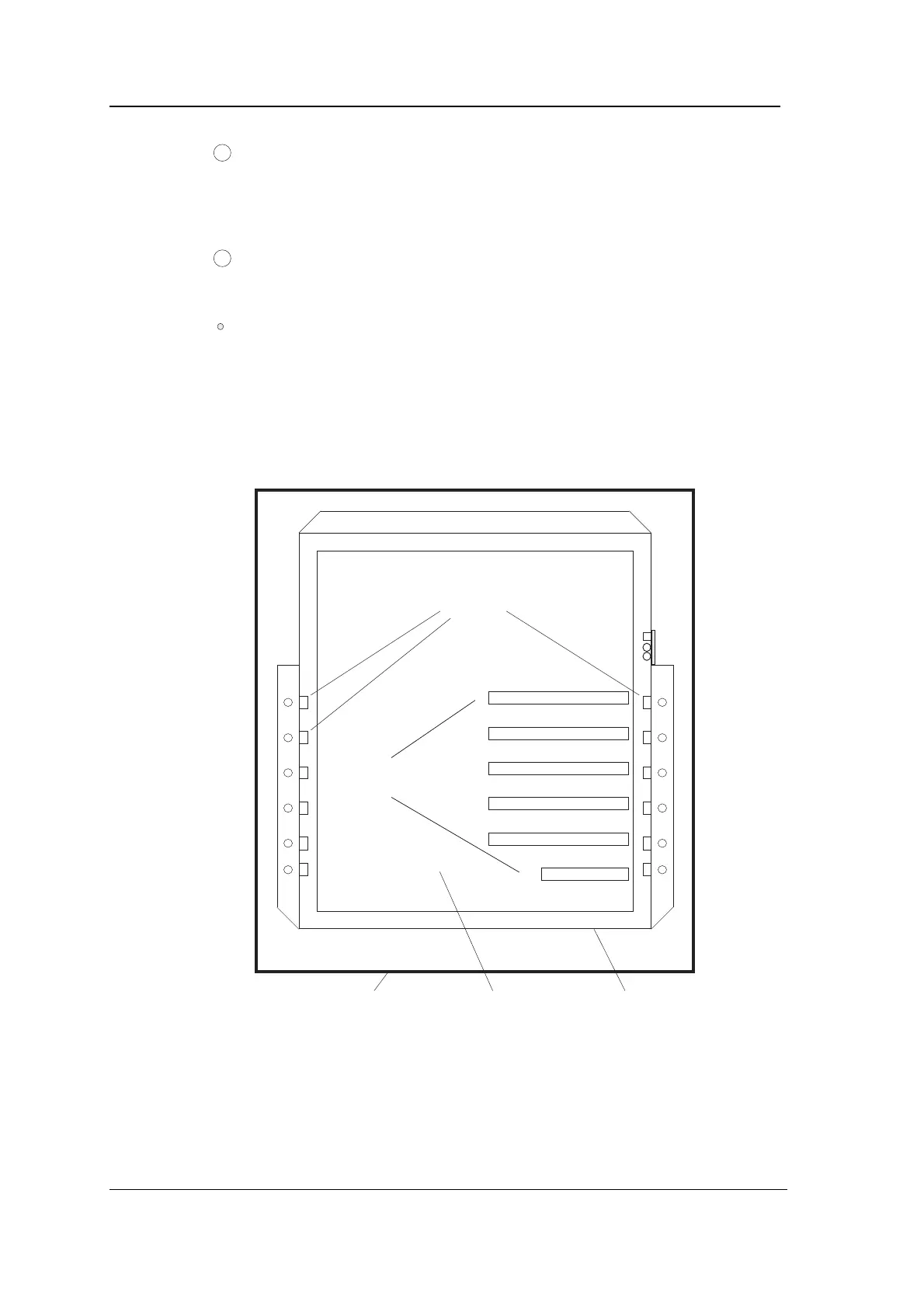
The following diagram shows the components of the 4101-2
Controller and its six module slots.
Module
slots
Case Motherboard Chassis
Module
guides
0
2
4
6
89
1
3
5
7
Module
slots
The 4101-2 Modular Controller is made up of a case (the part which
you fix to the wall), a chassis (which can easily be removed from the
case), and a lid. A PCB called the “motherboard” and a much smaller
PCB containing the tamper switch and two LED indicators are
mounted on the chassis. The motherboard has five full-size module
slots, and one smaller module slot which is used only for the 4210 RF