4101-2 Controller Installation Handbook
15-8
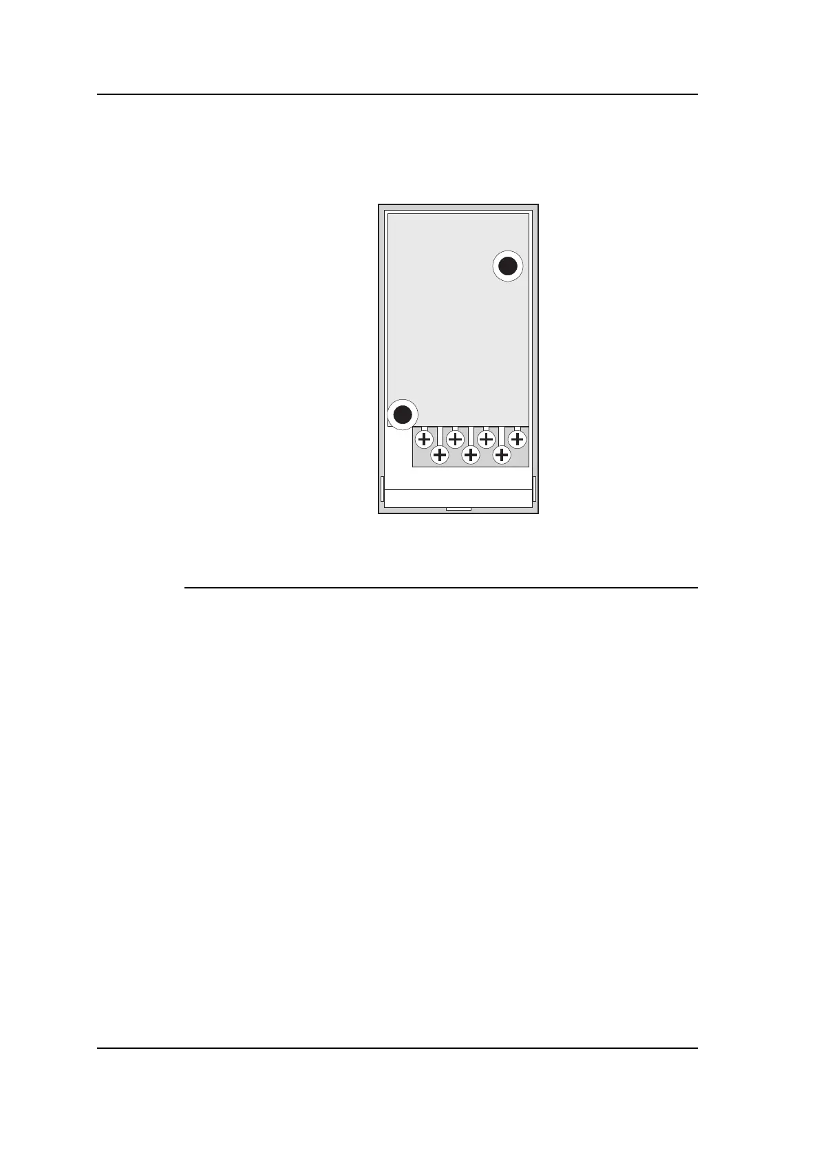
Connecting the 090 Reading Head
The connector on the 090 Reading Head is laid out as follows:
Viewed from rear
1234567
The pin descriptions are as follows:
Pin Cable colour* Description
1 Black/Red Transmit line
2 Black/Red Transmit line
3 Brown LEDs common anode (+ve)
4 Red Red LED cathode (-ve)
5 Green Green LED cathode (-ve)
6 Black/White Receive line
7 Black/White Receive line
*
This column shows the recommended cable colour for each function
when you use 812 cable.
Notes:
• The cable screens should be connected at the Controller only.
At the Reading Head they should be cut back and insulated.
See the chapter on “Earthing and screening”.
• A break-out box can be used between the main feeder cable(s)
and the Reading Head. See the chapter on “Cables” for details.
Loop antennas
Please read the Loop Antenna Installation Handbook HB02/106 for
details of how to choose, design and install a loop antenna.