4101-2 Controller Installation Handbook
3-8
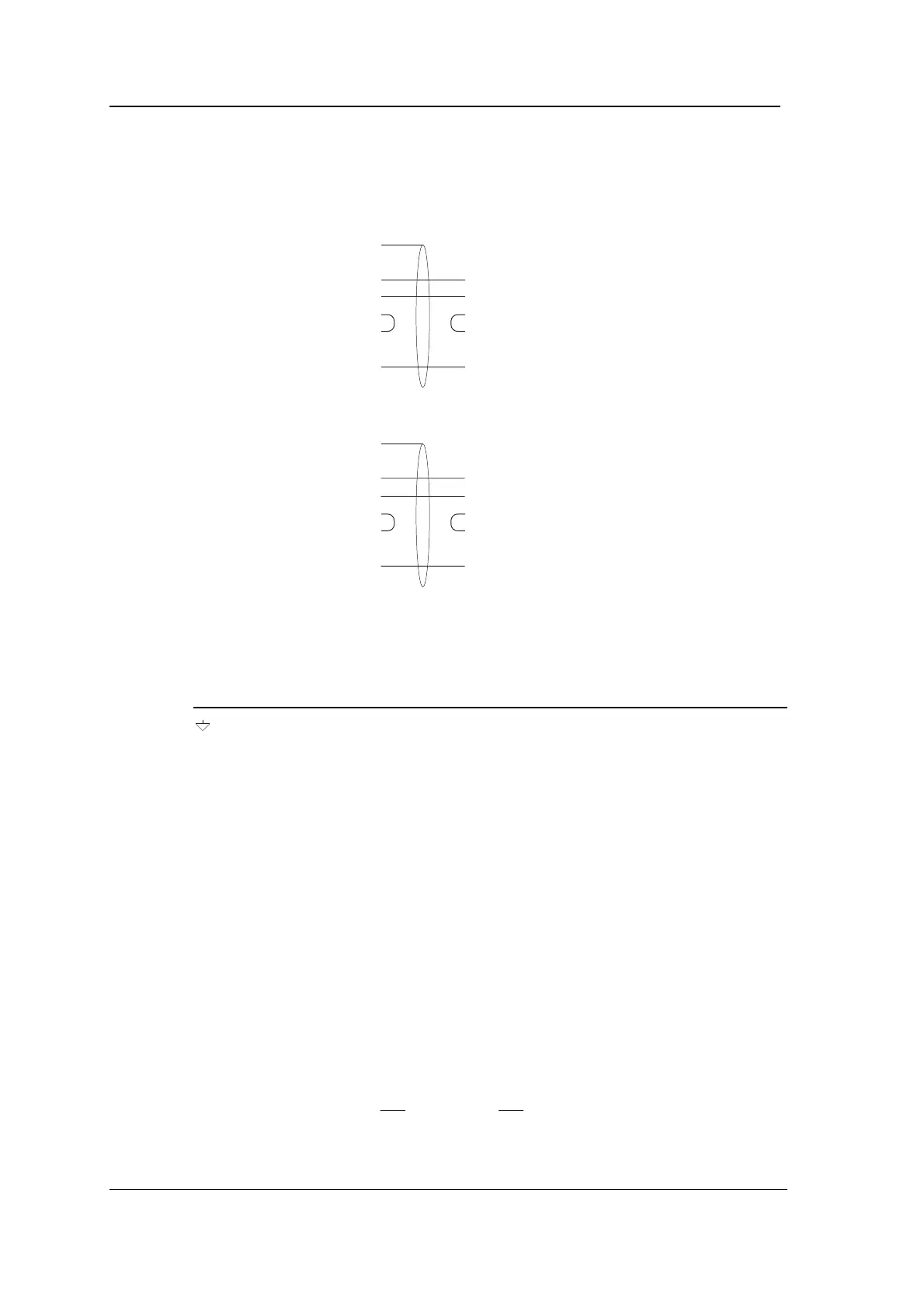
Note: CTS and RTS should be linked together both at the computer
and at the Controller as shown in the diagrams below.
PC: 9-way COM1:
2 RXD
3 TXD
8 CTS
7 RTS
5SE
Controller
Connect cable screen
to Controller case
TXD
RXD
RTS
CTS
SE
Controller
Connect cable screen
to Controller case
TXD
RXD
RTS
CTS
SE
PC: 25-way COM1:
3 RXD
2 TXD
5 CTS
4 RTS
7SE
Connection to Radio Controlled Clock
Cable
: 2-core, overall screened.
Pin Function Connection
Screen No connection
RXD Receive Data to 5810 Converter pin 2
TXD Transmit Data No connection
CTS Clear To Send connect to RTS on CONN1
RTS Ready To Send connect to CTS on CONN1
0V Signal Earth to 5810 Converter: pin 7
CONN2
Function
: RS485 connection from Comms module, daisy chained to
all Controllers in one branch of the system. Do not use this connector
if you are using CONN1, except in a master/slave configuration using
two Controllers, or if you are using CONN1 to connect the Radio
Controlled Clock.
Cable
: twin individually screened twisted pairs, maximum length
1000 metres in total (whole branch), for example Belden 8723.
Normal connection using Comms module
:
Connect CONN2 RX,
, TX and
pins to corresponding pins of
CONN2 on next and previous Controllers. Connect cable screens to