4101-2 Controller Installation Handbook
8-12
to the screw terminals with a screwdriver. Unplugging the connectors
also enables the module to be removed at a later date, leaving the
wiring intact.
Connecting the Comms module to the computer and
Controllers
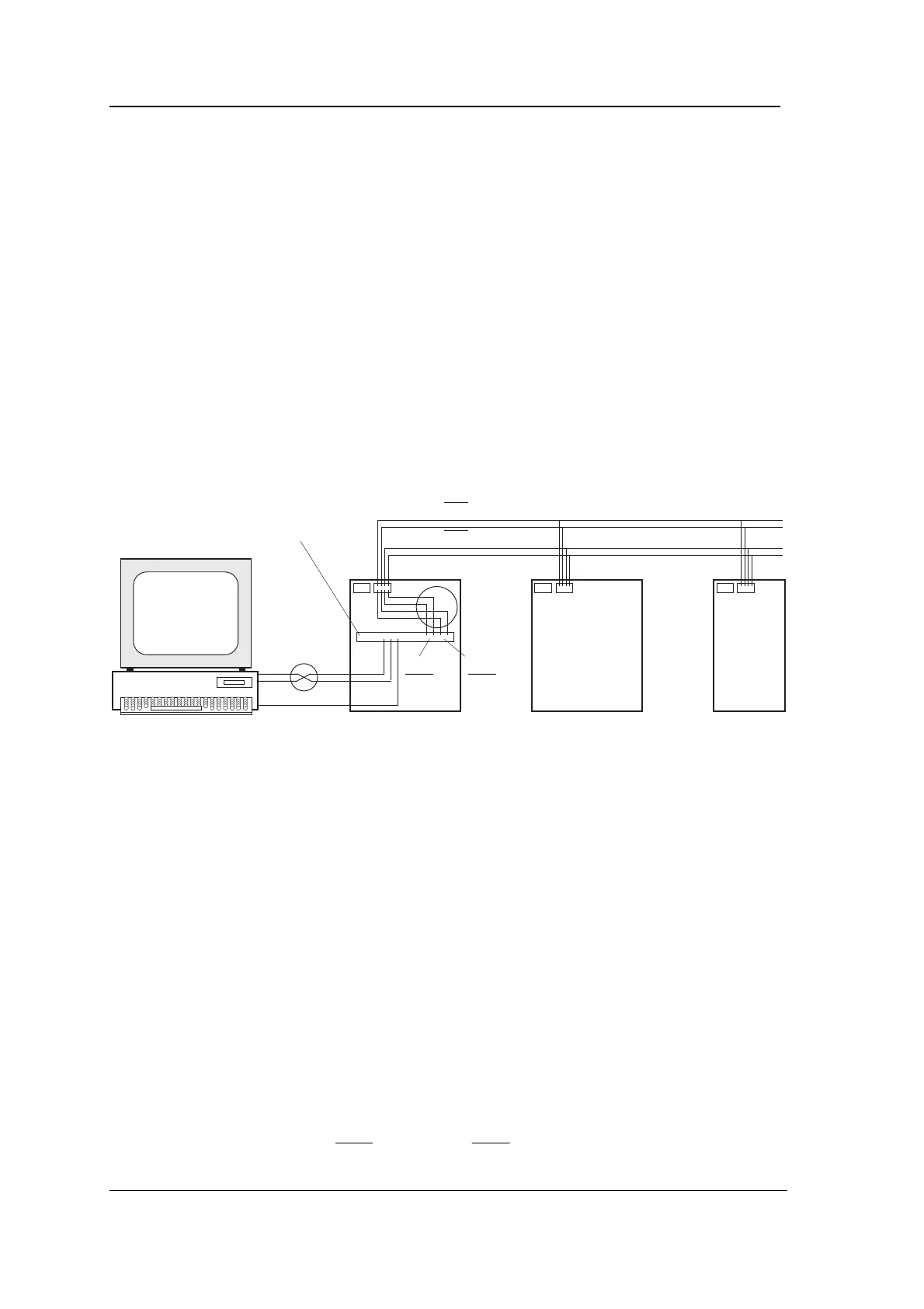
The following diagram shows how the transmit and receive signals
are linked for a Local Hardware System with one Comms module.
Connecting the comms has been found to cause confusion among
installers, so we hope this diagram will help. Notice the two points
where Tx and Rx are swapped (shown inside the two circles in the
diagram). The first is between the computer’s serial port and the
upstream RS232 connections of the Comms module. The second is
between the downstream RS485 connections of the Comms module
and the Controller motherboards.
Computer
RXD RXD
TXD TXD
SE SE
Comms
module
RS232
RS485
RXD/RXD
TXD/TXD
RXD
RXD
TXD
TXD
Note the following points carefully:
1. The computer connections are made between the upstream
RS232 on the Comms module and the serial port of the PC
(which may be either a 9-way or a 25-way D-type connector).
Only three signals are connected - TXD, RXD and SE.
Tx and Rx connections from the computer to the Comms
module must be swapped: TXD on the Comms module goes to
RXD on COM1:, RXD on the Comms module goes to TXD on
COM1:.
2. CTS and RTS must be linked together at the computer and
also at the Comms module, but connections from CTS and
RTS must not be made between the computer and the Comms
module.
3. The Controller connections are made between the downstream
RS485 on the Comms module to CONN2 of all the
motherboards on the branch. Only four signals are connected -
TXD and
, RXD and
.