4101-2 Controller Installation Handbook
3-6
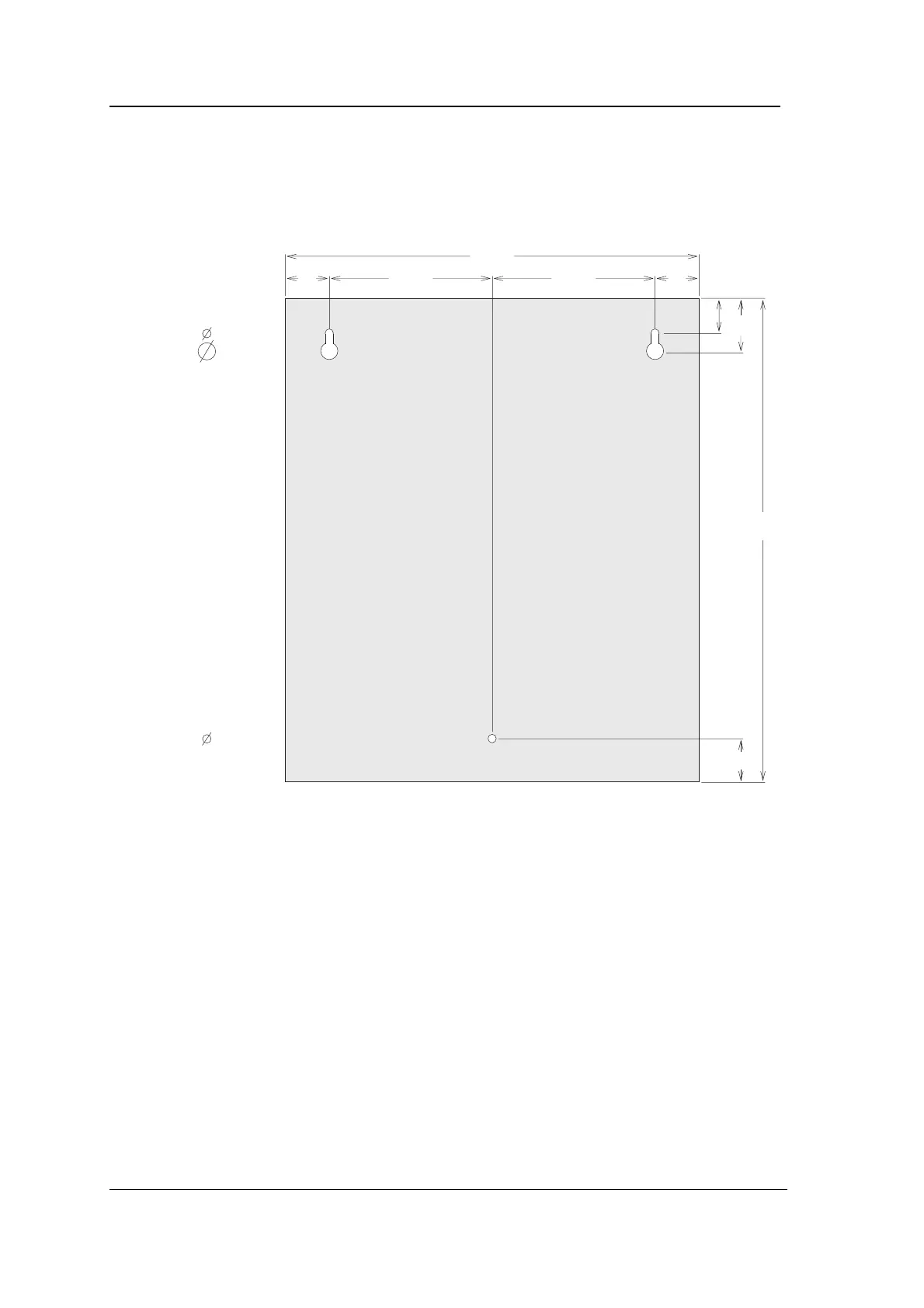
3. Mark out and drill three mounting holes for the case and screw
it in position on the wall, checking that the cable entry points
are accessible. Do not forget to route cables first, especially if
you are using the cable entry points in the back.
dimensions
in mm
30 118 118 30
296
31
346
36
25
= 6
= 10
= 6
4. Replace the chassis and tighten the two fixing screws.