110
Applications
Application Bulletin (.pdf) files are available in the DOCS folder on the Audia software CD-ROM. The
associated design (.dap) files for these applications are included in the SAMPLE FILES folder, as example
references.
Hardware
Hardware Overview
Audia
®
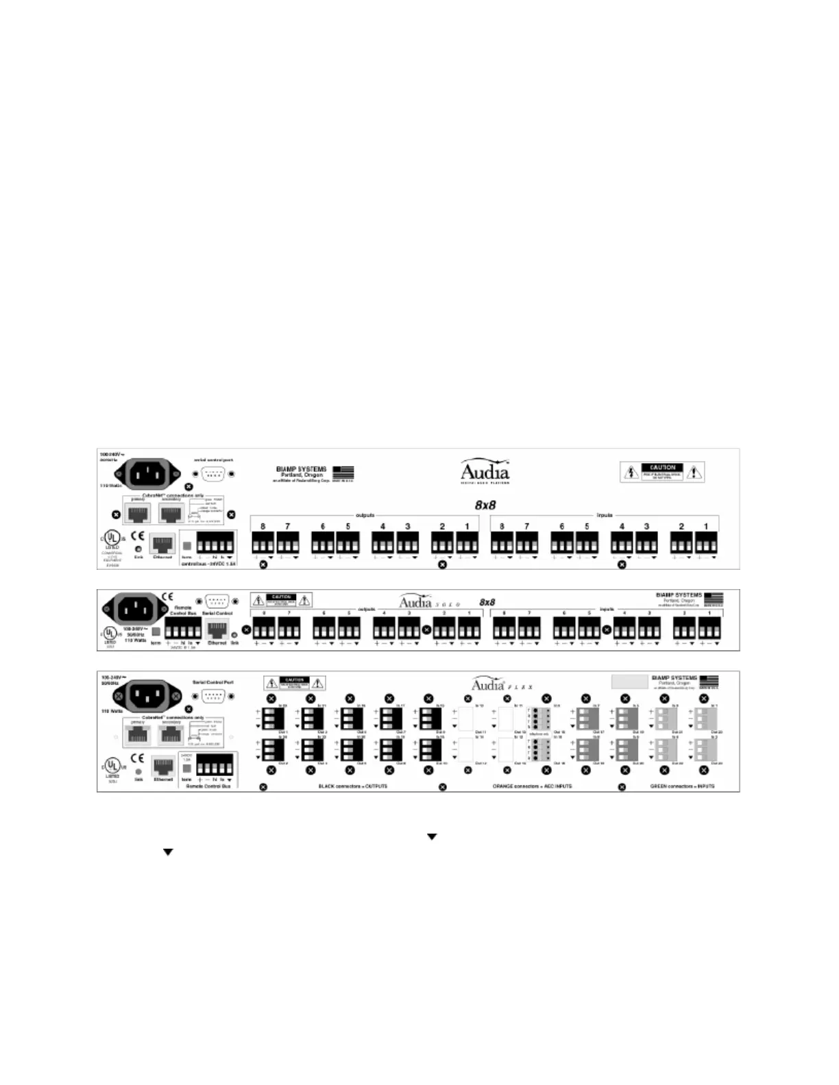
hardware is represented by three different chassis models: standard Audia; AudiaSOLO; and
AudiaFLEX. Standard Audia is a 2RU CobraNet™ only chassis and AudiaSOLO is a 1RU non-CobraNet
only chassis. These two chassis are available in three I/O configurations: 8-in & 8-out (8x8); 12-in & 4-out
(12x4); 4-in & 12-out (4x12). AudiaFLEX is the newest chassis design, which allows up to 24
inputs/outputs, in any combination of channel pairs. AudiaFLEX is available with or without CobraNet.
Inputs & outputs are analog, with internal 24-bit A/D & D/A converters, operating at a sample rate of 48kHz.
All internal processing is digital (DSP). CobraNet 8-channel Input & Output Expanders are also available.
Inputs & Outputs: Inputs & outputs are provided on balanced plug-in barrier-strip connectors. For
unbalanced input, wire high to (+) and ground to both (
) & (-). For unbalanced output, wire high to (+) and
ground to (
), leaving (-) un-connected. With Audia and AudiaSOLO, inputs can be individually
programmed to accept either microphone or line level signals. A 12x4 configuration allows Inputs 11 & 12
to be set for stereo input summing. Outputs normally provide line level signal only. However, a 4x12
configuration allows Outputs 1~4 to be set for microphone level. AudiaFLEX inputs and outputs can be
individually selected for microphone or line level operation. Besides standard 2-channel cards for input
(IP2) and output (OP2e), AudiaFLEX hardware can use special Acoustic Echo Cancellation (AEC2w) and
Telephone Interface (TI-2) cards. NOTE: Connections to a telephone network must be made by qualified
personnel, using #26 AWG solid copper wire for continued safety (T = tip; R = ring).