117
Remote Control Bus
Remote Control Bus provides the connection for Volume 8, Select 8, Volume/Select 8, and Logic Box
external control devices.
Each Audia
®
device can support any combination of the controls mentioned above. Up to 32 controls may
be connected to each Audia device, on a daisy-chain 'network', with a maximum cable length of 1000 feet
(300 meters). Controls are wired in parallel (pin-for-pin), using 5-conductor data grade cable (95~120 ohms
nominal impedance; 16 pF/ft. max. capacitance; 65% min. velocity of prop.).
Recommended cable
: Gepco UNC220 or equivalent
(use data pair for Hi & Lo; use power pair for + & -).
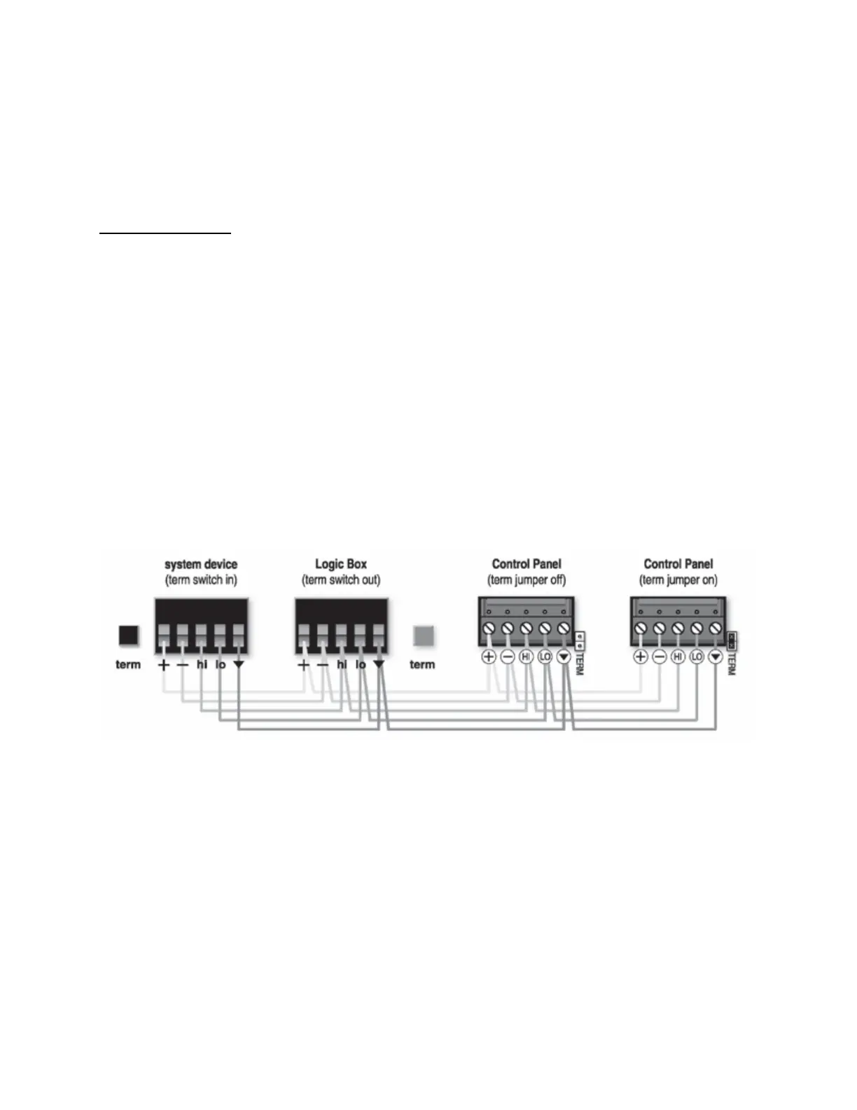
The 'network' requires termination at each 'end' for proper operation. All controls (and Audia) include either
a termination switch or jumper strap. These terminations should be disabled (switch out or jumper
removed) on all devices except those at the two extreme ends of the network. (See wiring diagram below).
A control network may be wired with the Audia device at one end, and a control device at the other end,
creating one continuous run. In this case, the Audia device would have the 'term' switch engaged (in), and
the control device at the other end of the network would have the 'term' switch engaged (in) or jumper
installed. All other controls, between the Audia device and the last control, would have their 'term' switches
released (out) or jumpers removed.
If a control network needs to service two areas which are in opposite directions from the Audia device, a
network with two separate runs can be created. This type of network actually remains as a single run, but
is configured with the Audia device in the middle. Therefore, only the controls at the two extreme ends of
the network would have their 'term' switches engaged (in) or jumpers installed. All other controls (including
the Audia device), between the two end controls, would have their 'term' switches released (out) or jumpers
removed. (See network diagrams below.)