CB (E7) 06/2018 Page 93/174
11.6 Zero-voltage relay alarm output
The chamber is equipped with a zero-voltage relay output which permits the
transmission of some alarm messages to a central monitoring system.
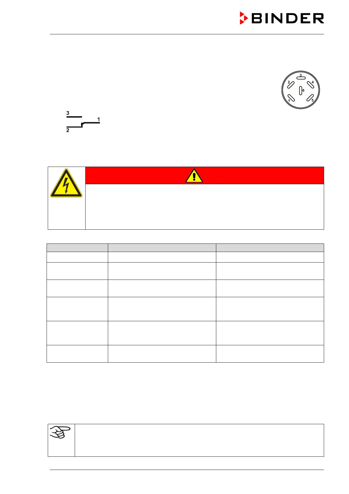
The connection is realized as a DIN socket (3
) on the chamber rear. A suitable DIN
plug is enclosed.
Figure 20: Pin configuration of the DIN socket (3
ALARM
Pin 1: Pole, Pin 2: Break relay, Pin 3: Make contact
In case there is no alarm, contact 1 closes with contact 3.
Closing contact 1 with contact 2 switches the zero-voltage relay alarm output.
Maximum loading capacity of the switching contacts: 24V AC/DC – 2.5A
DANGER
Electrical hazard.
Danger of death.
Damage to switching contacts and connection socket.
∅ Do NOT exceed the maximum switching load of 24V AC/DC – 2.5A.
∅ Do NOT connect any devices with a higher loading capacity.
The zero-voltage relay alarm output switches at the following events:
Switching the alarm contact
---
Power failure immediately
“Temperature range”
Temperature tolerance range alarm
(see chap. 11.1.2)
After configurable delay time (chap.
11.5). Factory setting: 10 minutes
“CO2 range”
CO
2
tolerance range alarm
(see chap. 11.1.2)
After configurable delay time (chap.
11.5). Factory setting: 10 minutes
“O2 range”
O
2
tolerance range alarm
(chamber with O
2
control)
(see chap. 11.1.2)
After configurable delay time (chap.
11.5). Factory setting: 10 minutes
“Humidity range”
Humidity tolerance range alarm
(chamber with active humidification)
(see chap. 11.1.2)
After configurable delay time (chap.
11.5). Factory setting: 10 minutes
“Door open”
Chamber door open alarm
(see chap. 11.1.2)
After configurable delay time (chap.
11.5). Factory setting: 1 minutes
In case of a tolerance range alarm or a door open alarm, the alarm message on the controller display
remains on during the alarm transmission via the zero-voltage relay outputs.
As soon as the cause of the alarm is identified and resolved, you can reset the alarm transmission via the
zero-voltage relay outputs together with the alarm message in the “Active alarms” menu by pressing the
Reset alarm icon.
In case of a power failure, transmission of the alarm via zero-voltage relay outputs remains active for the
duration of the power failure. After power returns, contact 1 closes automatically with contact 3.
When using the communication software APT-COM™ 3 DataControlSystem (option, chap.
18.1) for data acquisition, the alarm messages are only recorded in the protocol.
Set the tolerance limits for limit alarms by APT-COM™ 3 separately in the APT-COM™ 3
measuring window.