CB (E7) 06/2018 Page 2/174
Contents
1. SAFETY .................................................................................................................. 7
1.1 Legal considerations ........................................................................................................................... 7
1.2 Structure of the safety instructions ...................................................................................................... 7
1.2.1 Signal word panel ..................................................................................................................... 7
1.2.2 Safety alert symbol ................................................................................................................... 8
1.2.3 Pictograms ................................................................................................................................ 8
1.2.4 Word message panel structure ................................................................................................. 9
1.3 Localization / position of safety labels on the chamber .................................................................... 10
1.4 Type plate ......................................................................................................................................... 11
1.5 General safety instructions on installing and operating the CO
2
incubator ...................................... 12
1.6 Precautions when working with gases .............................................................................................. 13
1.7 Precautions when handling gas cylinders ......................................................................................... 15
1.8 Intended use ..................................................................................................................................... 16
1.9 Measures to prevent accidents ......................................................................................................... 17
1.10 Resistance of the humidity sensor against harmful substances ....................................................... 18
2. CHAMBER DESCRIPTION .................................................................................. 19
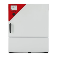
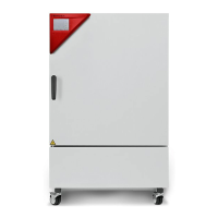
2.1 Chamber overview ............................................................................................................................ 20
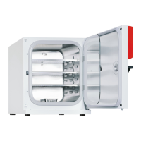
2.2 Inner chamber ................................................................................................................................... 21
2.3 Control panel on the rear of the chamber ......................................................................................... 22
2.4 Instrument panel ............................................................................................................................... 23
3. COMPLETENESS OF DELIVERY, TRANSPORTATION, STORAGE, AND
INSTALLATION .................................................................................................... 23
3.1 Unpacking, and checking equipment and completeness of delivery ................................................ 23
3.2 Guidelines for safe lifting and transportation..................................................................................... 24
3.3 Storage .............................................................................................................................................. 24
3.4 Location of installation and ambient conditions ................................................................................ 25
4. INSTALLATION AND CONNECTIONS ............................................................... 28
4.1 Shelves.............................................................................................................................................. 28
4.2 Permadry™ water pan ...................................................................................................................... 28
4.3 Connecting the O
2
sensor (chamber with O
2
control) ....................................................................... 29
4.4 Gas connections ............................................................................................................................... 30
4.4.1 Connection of the CO
2
gas cylinder ........................................................................................ 31
4.4.2 Connection of the O
2
gas cylinder (chamber with O
2
control with optional alternative control
range 10 up to 95 vol.-% O
2
) .................................................................................................. 32
4.4.3 Connection of the N
2
gas cylinder (chamber with O
2
control)................................................. 33
4.4.4 Connecting the gas hose to the chamber rear (for CO
2
, O
2
, N
2
) ............................................ 34
4.4.5 Gas cylinder connection kits (option) ...................................................................................... 35
4.5 Water supply for the chamber with active humidification .................................................................. 36
4.5.1 Types of suitable water quality ............................................................................................... 36
4.5.2 Water supply installation ......................................................................................................... 37
4.5.3 BINDER Pure Aqua Service (option) ...................................................................................... 37
4.6 Electrical connection ......................................................................................................................... 38
4.7 Handling and aligning the divided inner door, gas proof (optional equipment) ................................. 39
5. FUNCTIONAL OVERVIEW OF THE MB2 CHAMBER CONTROLLER ............... 40
5.1 Operating functions in normal display ............................................................................................... 41
5.2 Display views: Normal display, program display, chart-recorder display .......................................... 42
5.3 Controller icons overview .................................................................................................................. 43
5.4 Operating modes ............................................................................................................................... 45
5.5 Controller menu structure .................................................................................................................. 46
5.5.1 Main menu .............................................................................................................................. 47
5.5.2 “Settings” submenu ................................................................................................................. 48
5.5.3 “Service” submenu .................................................................................................................. 48