Introduction 11
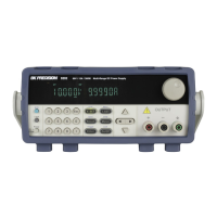
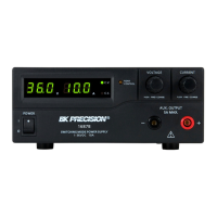
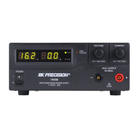
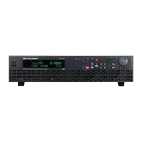
1.6 Display
Figure 1.3 Display
Item Description
1 Measured voltage
2 Settings voltage and current
3 Measured power output
4 Measured current
OFF Indicates output is disabled
CC Indicates constant current (CC) operation
CV Indicates constant voltage (CV) operation
RMT Indicates remote mode
Addr Indicates remote communication activity
Error Indicates an error has occurred
Shift Indicates shift mode (access to secondary button functions)
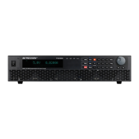
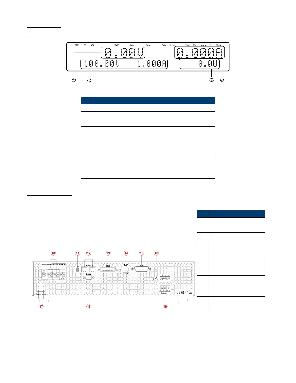
1.7 Rear Panel
Item Description
10 Output
11 USB Interface
12 RS-485 Interface
13
Analog Programming
Interface(DB25 Connector)
14 Ethernet (LAN) Interface
15 GPIB Interface
16 Earth ground connection
17 Remote sense terminals
18
RS-232 interface
& fuse box
19
AC input receptacle
& fuse box