Getting Started
Before connecting and powering up the instrument, please review and go through the instructions in this chapter.
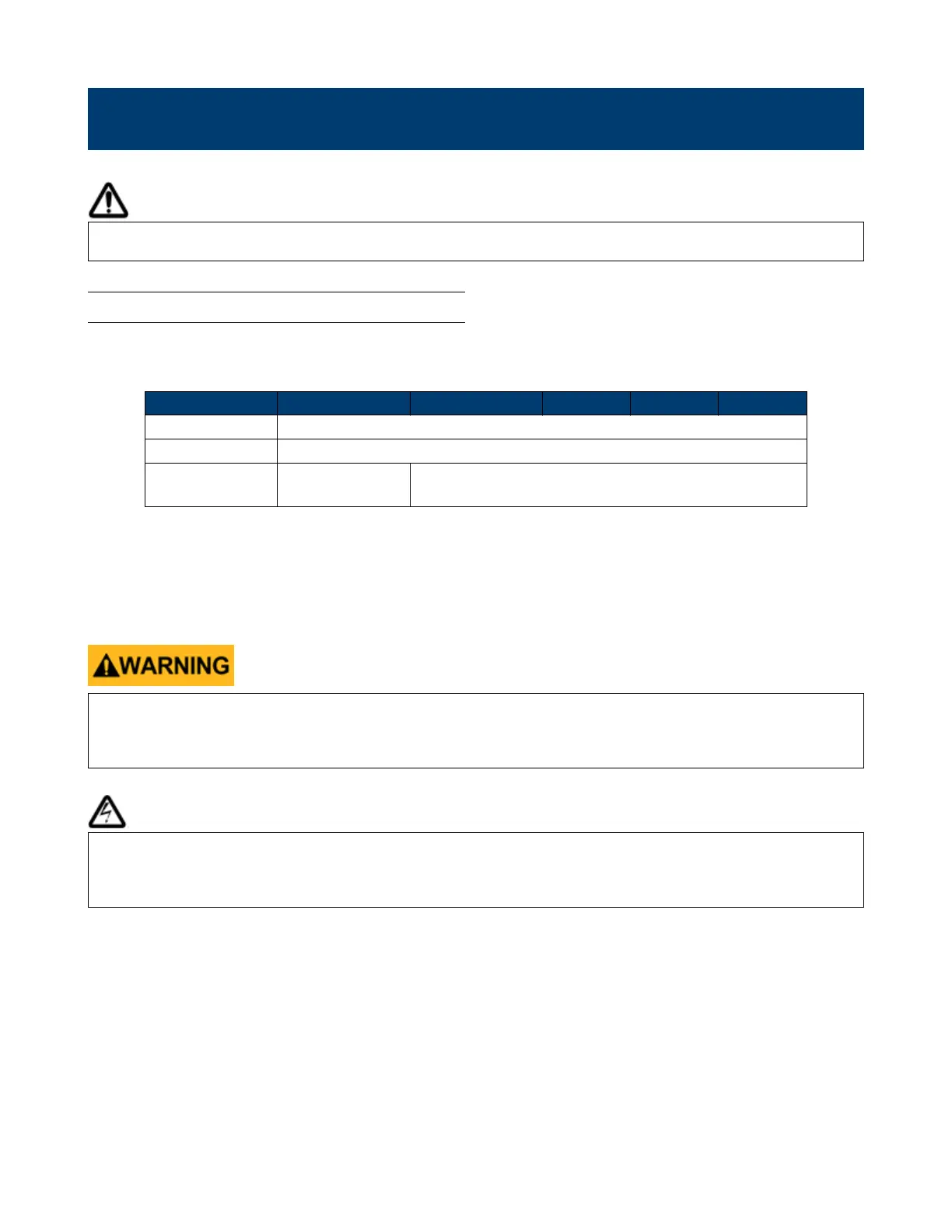
2.1 Input Power and Fuse Requirements
The supply has a universal AC input that accepts line voltage input within:
Model MR3K160120 MR160120 MR25080 MR50040 MR100020
AC Line Input 200 to 240 VAC ± 10%, 47 Hz to 63 Hz
AC Line Phase Single phase
Maximum Rated
Input Power
4000 VA 6000 VA
Table 2.1 Input Power and Fuse Requirements
Before connecting to an AC outlet or external power source, be sure that the power switch is in the OFF position and
verify that the AC power cord, including the extension line, is compatible with the rated voltage/current and that there
is sucient circuit capacity for the power supply. Once veried, connect the cable rmly.
The included AC power cord is safety certied for this instrument operating in rated range. To change a cable or add
an extension cable, be sure that it can meet the required power ratings for this instrument. Any misuse with wrong
or unsafe cables will void the warranty.
SHOCK HAZARD:
The power cord provides a chassis ground through a third conductor. Verify that your power outlet is of the three-
conductor type with the correct pin connected to earth ground.
Follow the instructions below to connect the AC power cable to the AC input of the power supply in the rear panel.
1. First, connect the input receptacle (green terminal block) of the cable to the input terminals of the power supply.
2. Align the power cord housing mounting holes on the left and right side to the screw holes on the power supply.
3. Use only the included screws to fasten and secure the cable housing assembly.