145
Task Procedures Illustrations
LEGACY
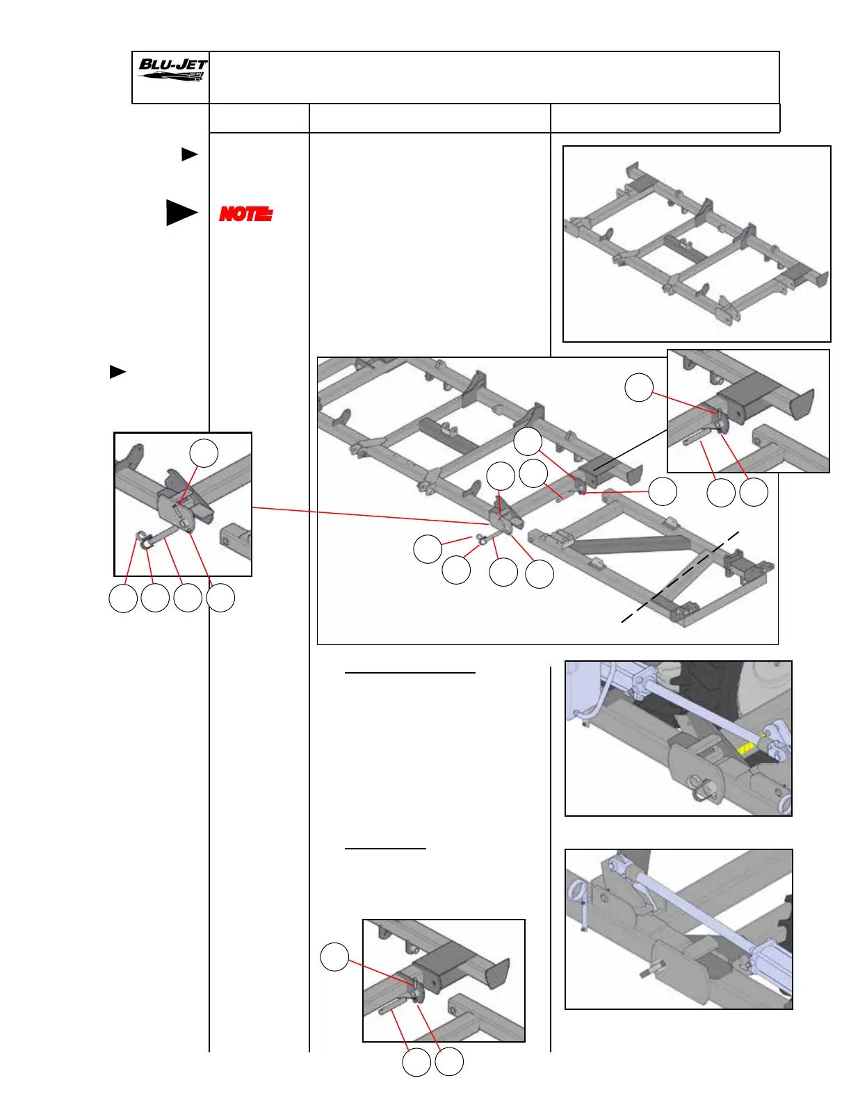
1. Place (AM6172) main frame
on sturdy stands, about 36”
high on hard level surface.
2. Position primary wings
(AM6187) left-hand and
AM6188) right-hand) on
main frame with forklift.
Secure wings to main frame
front and rear hinges with (a)
(BM3485) 1-3/4” x 11-13/16”
OAL, W/21/32 hole, pins
.
3. Tractor Side Hinges
Place (b) (AM4415) open loop
hose retainer and (c)
(AM4442) closed loop hose
retainer over main frame hinge
weldment and insert (d) (BP3136)
5/8” x 4”, grade 5 plated hex
cap screw through assembly.
Secure with (e) (BP3375) 5/8”
hex lock nut (Nylock).
4. Rear Hinges
Insert (d) (BP3136) 5/8” x 4”,
grade 5 plated hex cap screw.
Secure with (e) (BP3375) 5/8”
hex lock nut (Nylock).
Assembly
Positioning
main frame
on stands
Attaching
primary
wings
NOTE:
Left-hand
and
right-hand
as viewed
from the
rear.
Left-hand from the rear
Right-hand from the rear
Left-hand from the rear
Tractor side
Position stand
under wing in this area
a
d
c
b
a
e
d
a
eb
c
d
e
a
d
Tractor side
Tractor side
e
a
d
Rear
e