Task Procedures Illustrations
212
LEGACY
1. Consult row spacing pages
and mark out spacing on
front and back bars.
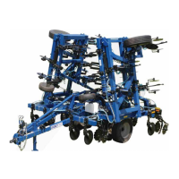
2. Consult row spacing page
and position (a) (AM24025) pin
adjust gauge wheel bracket
on mainframe and secure
with two (b) (BP3350) 3/4-10
x 6”W x 7-7/16”L u-bolts,
four (c) (BP3035) 3/4” lock
washers and four (d) (BP3034)
3/4” hex nuts.
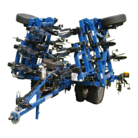
3. Position (e) (AM24024) pin
adjust gauge wheel assembly
leg into mounting bracket
and insert (f) (BM3650) 1” x
5-9/16” double grooved pin.
4. Secure pin with two (g)
(BP3215) 1-1/2” machinery
bushing 1-1/2” OD x 1” ID
14 GA and two (h) (AP2407)
1” snap rings heavy duty on
both ends of the pin.
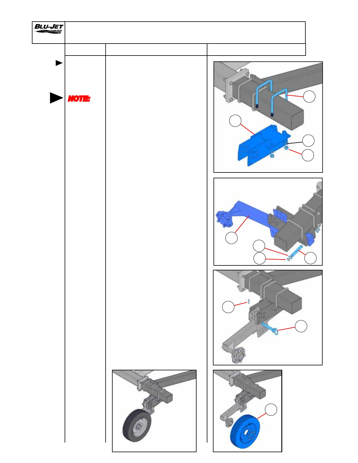
5. Insert (i) (BP3051) 1” x 6” pin
into middle hole of middle
row on the mounting bracket.
Secure with (j) (BP 3511) 3/16” x
1-3/4” cotter key.
6. Remove hex cap screws
from wheel leg hub and
mount (k) (AAM2768) 25 x
7.50-15 4 ply tire and rim on
hubs. Secure with hex cap
screws. Wheels face to the
outside of the mainframe.
Pin Adjust Gauge Wheel Assembly
Mounting
pin adjust
gauge
wheels
NOTE:
Consult
row spacing
pages for
pin adjust
gauge
wheel
locations
b
d
c
e
f
g
h
i
j
k
a
 Loading...