227
Task Procedures Illustrations
LEGACY
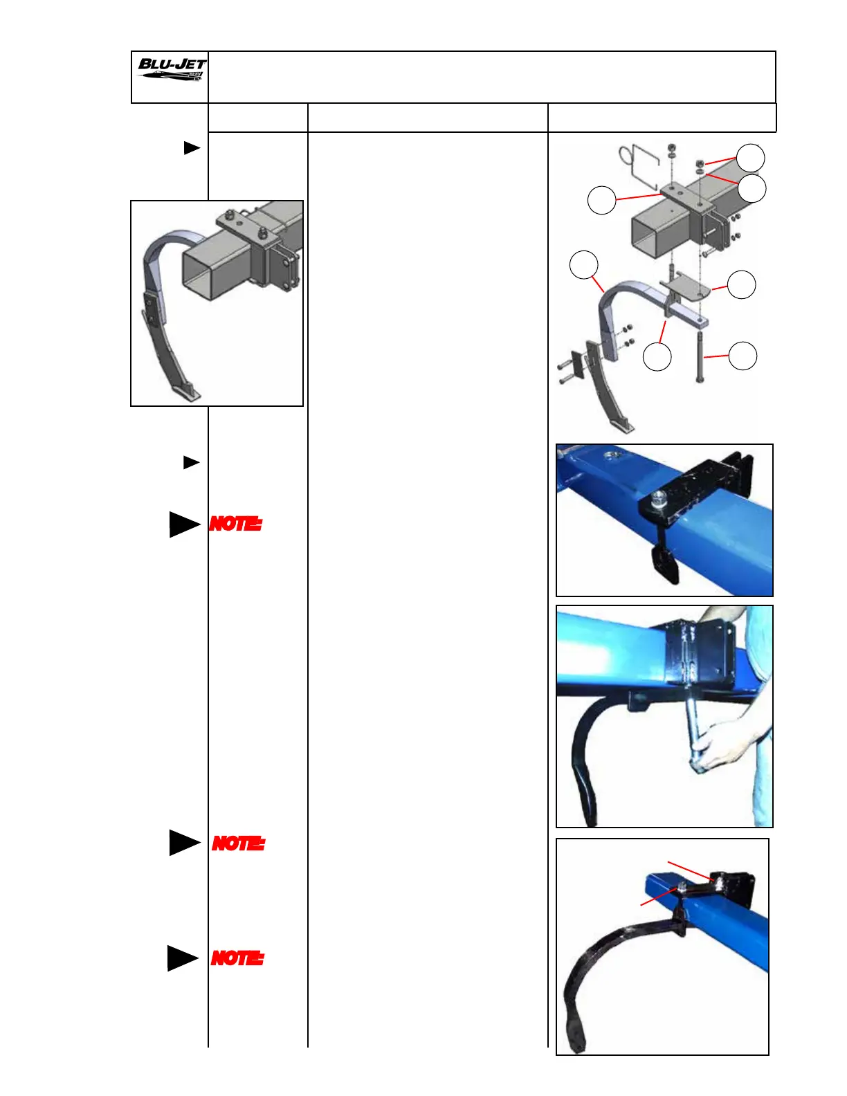
1. a. AM2148 1 Clamp, square
hole 6”
mounting,
coil & at
b. AM2188 1 Backing plate
c. AM2742 1 Bracket,
universal
coulter 6”
d. AP2063 1 1” x 2” at
shank
e. BP3034 2 Nut, hex, 3/4”-
10, grade 2,
plated
f. BP3035 2 Washer, lock
3/4”, plated
g. BP3578 1 Hex, cap screw,
3/4”-10 x 9-1/2”
grade 5 plated
2. Center (c) (AM2742) universal
bracket on row spacing marks.
Insert (a) (AM2148) square hole
clamp through rear hole in
universal bracket.
Place (f) (BP3035) 3/4” lock
washer and (e) (BP3034) 3/4”
hex nut on square hole clamp
threads.
3. Insert (d) (AP2063) 1” x 2” at
shank into square hole clamp
until shank hole aligns with
universal bracket top hole.
Place (b) (AM2188) backing
plate on shank.
Insert (g) (BP3578) 3/4” x 9-1/2”
hex cap screw from the
bottom. Place (f) (BP3035) 3/4”
lock washer and (e) (BP3034)
3/4” hex nut on hex cap screw.
4. Snug-up the square hole clamp
hex nut rst. Tighten the hex
cap screw hex nut next.
Check both hex nuts for
tightness.
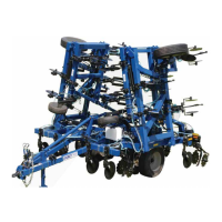
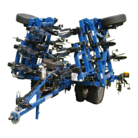
Shank Assembly and Mounting
1” x 2” at
shank parts
Mounting
1” x 2” at
shank
NOTE:
The at
side of the
square hole
clamp must
face the
tube
NOTE:
Check
bracket t.
Brackets
should t
at against
the tube
Tighten rst
Tighten second
Generic Photo
Generic Photo
Generic Photo
NOTE:
No threads
in shear
area when
attaching
knives
a
b
c
d
f
e
g
 Loading...